Interpolation of bed leveling points
On my MK3 I recently releveled my bed and end at 48um. The process is very easy and straight forward and makes a difference in the final product.
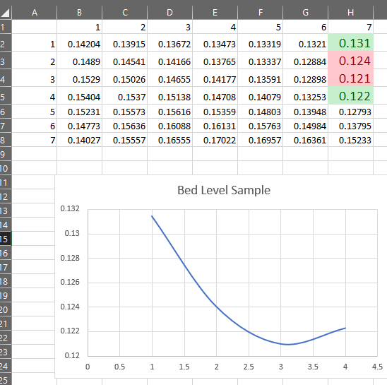
While in the process of the leveling I began looking at the data returned by G81. Points 1,4,7 are directly measured on both the X and Y axis.
Something just did not look right with the interpolated points. I entered them into excel and plotted the result.
I had assumed that the data interpolation would be linear, however; the plot showed it was far from it.
Looking at the sorce code I see that Lagrange interpolating polynomials are implemented. These should still be linear.
So my concerns are, why are the interpolated points not linear? What effect does this have on the Z corrections? and can someones elseverify the results I have found?
Thank you,
Ron
Re: Interpolation of bed leveling points
I suspected the interpolation was not appropriate. And you confirm it. That is why I try to get a flat bed, to avoid that kind of interpolation.
The bed may have slope but it has to be flat as I don't trust the implemented interpolation.
Re: Interpolation of bed leveling points
If you could post your g81 data it would be great. Then I need to get the attention of the developers
Re: Interpolation of bed leveling points
Two other users shared there G81 data and here are their results.
It is now obvious that thee is an issue with the interpolation that needs to be addressed.
Re: Interpolation of bed leveling points
Can you give a clearer explanation of why you think the distortion of the heatbed will be linear? My take on the use of lagrangians is as follows:-
The distorted heatbed shape is much more likely to follow a curved path, with inflections at the bolt locations. The heatbed is held to a given shape by the fixings at the bolt locations, and no-where else. It's the same effect as the shape a plastic ruler takes when you flex it between your fingers; the surface of the ruler follows a curved path between the points where a force is applied. Note that the plastic ruler will remain straight outside of the constrained region, but that our distorted heatbed is almost entirely within the region constrained by the bolts, and hence will end up in a curved shape.
Lagrangians get used in engineering, (in finite element modelling) to represent exactly this sort of bending behaviour. It's certainly what I'd use if I had to model the distortion of a plate with only a few known points. I think that in this case, the accuracy is being limited by the number of known points rather than by the algorithm used. There may be edge cases where linear interpolation will be more accurate, but they should be few and far between
Re: Interpolation of bed leveling points
Interesting point. The next step then would be to use a high resolution dial indicator and tram the bed at operating temperatures.
I don't know if I have seen a dial indicator with that high a resolution however. At least not one I can aford.
Re: Interpolation of bed leveling points
So looking at the thermal stress deflection and making the assumption that the screws holding the heated bed to the Y carriage are ideally rigid and that there is no growth of the Y carriage due to the proximate heat of the bed, the maximum deflection between two screws is 52.6 um down on the x axis and 44. 1 um down on the y axis. This is at a bed temp of 60C or 35C rise.
At a bed temp of 100C the deflection is 85.6 um on x and 71.8 on Y.
Therefore it seems you are correct that the interpolation is not suppose to be linear.
Re: Interpolation of bed leveling points
I still don t have data to share from a tuned printer. hope soon.
in my point of view, the lagrangian interpolation can give more error than a linear one in that case, particularly when the measurements are not so accurate.
And remember that the deformation is not static due to the heat if you don't do a warm up.
the "front left side" interpolation of matthias is strange to me.
Re: Interpolation of bed leveling points
Interesting point. The next step then would be to use a high resolution dial indicator and tram the bed at operating temperatures.
I don't know if I have seen a dial indicator with that high a resolution however. At least not one I can aford.
take a look on ebay for your area.
search for dial indicator 0.0001 this will indicate to ±0.0001 inch or 0.00254mm you should find them priced from $35 to $400 depending on age and who made them expect to spend $75 to $100 for a Starrett last wood in good used condition but your best buys will be for a lesser known high quality brand from the mid 20th century like Brown and Sharpe
here is a real bargain 0.0001 " dial indicator for example it is marked Bausch-and-Lombe the famous optical company but it is actually from a Brown & Sharp competitor Federal Instrument produced for and so marked for Bausch-and-Lombe to try to control "shrinkage" from their factories.

https://www.ebay.com/itm/Bausch-and-Lombe-Dial-Indicator-0-0001-SUPERB/292475974009?hash=item4418ed3179:g:mqAAAOSwOtVaoXHF:rk:13:pf:0
this has me tempted even though I have far more tools of this type in my machine shop
Re: Interpolation of bed leveling points
The fact that if I change spools of filament from a full to a near empty the frame flexes enough bed flatness of a fraction of a millimeter is of no concern since the change in weight just warped it again. The firmware does a reasonable job correcting for small bed deviations.
I'm more concerned with getting the frame true. When I build a cube, I don't want trapezoid error in any axis. Nor do I want twist as the Y-Axis move between stops (the two rods need to be parallel to each other and perpendicular to the X-Axis). Most of not all of my "bed flatness" is caused by the Y-Axis rods, and X-Axis upper end stop differences.
ps: non-linear interpolation is needed to compensate for the non-linear nature of the errors caused by bent metal and warped fiberglass. Pick up a piece of sheet metal and fit a line to it... just doesn't work well. Fitting a curve is much easier and provides a better interpolation. Whether the curve needs to be spherical or hyperbolic is another discussion.
Re: Interpolation of bed leveling points
If you could post your g81 data it would be great. Then I need to get the attention of the developers
Here my G81:
Recv: 0.11917 0.09926 0.08148 0.06583 0.05231 0.04093 0.03167
Recv: 0.10972 0.08746 0.06888 0.05398 0.04277 0.03524 0.03139
Recv: 0.10528 0.08187 0.06292 0.04843 0.03838 0.03280 0.03167
Recv: 0.10583 0.08250 0.06361 0.04917 0.03917 0.03361 0.03250
Recv: 0.11139 0.08934 0.07095 0.05620 0.04511 0.03767 0.03389
Recv: 0.12194 0.10240 0.08493 0.06954 0.05622 0.04499 0.03583
Recv: 0.13750 0.12167 0.10556 0.08917 0.07250 0.05556 0.03833