IN SEARCH OF: Meaningful Linear Advance Calibration
After benefitting from Jeff Jordan's excellent "Life Adjust" procedure for Live-Z calibration, I have been trying to produce a similar calibration process for fine-tuning Linear Advance settings. I've used the procedure and test prints from Matt's Hub and Marlin, and while they work, they suffer the same limitation as the on-board Live-Z calibration. They're dependent on the user interpreting the results of a single extrusion.
I've been trying to produce a Linear Advance calibration tower. I've created a tower print and custom Before layer change g-code:
BEFORE_LAYER_CHANGE

; layer_z is height of current layer in mm

G92 E0.0

;[layer_z]

{if layer_z == 111}M900 K55

{elsif layer_z == 101}M900 K50

{elsif layer_z == 91}M900 K45

{elsif layer_z == 81}M900 K40

{elsif layer_z == 71}M900 K35

{elsif layer_z == 61}M900 K30

{elsif layer_z == 51}M900 K25

{elsif layer_z == 41}M900 K20

{elsif layer_z == 31}M900 K15

{elsif layer_z == 21}M900 K10

{elsif layer_z == 11}M900 K5

{elsif layer_z == 1}M900 K0{endif}
I've verified that the gcode M900 Kxx lines are inserted as expected at the appropriate layers. And yet... they don't seem to make any impact on finish. Here's a print made using the Prusa SPEED profile:

Here's another made using my tweaked print profile:

(not exactly the same model, but the same gcode was used)
Can anyone suggest any ideas why changes in LA seem to make so little difference in print quality?
and miscellaneous other tech projects
He is intelligent, but not experienced. His pattern indicates two dimensional thinking. -- Spock in Star Trek: The Wrath of Khan Unfortunately,…
Re: IN SEARCH OF: Meaningful Linear Advance Calibration
LA comes into play and is most visible when there are *speed* changes in a straight section. Your tower probably does not have any in the straight sections, otherwise you'd see thinner and thicker parts.
A tower is also somewhat useless here, as you want to look at the top profile of the layer for each value to determine its effects, not the front face.
I've had excellent results with the one from Matt's Hub you linked. There is very little "user interpretation" there, the line is either uniform with a given K-value, or it has thick and thin spots where the speed changes and LA tries to compensate.
If multiple ones look good, choose the middle one.
No need to make a mountain out of a mole hill - I think you're grossly overthinking this.
Re: IN SEARCH OF: Meaningful Linear Advance Calibration
If I was designing a tower for this, I would make the face long enough for carriage to come to full speed.
Put lettering at extreme left end of face, so the lettering wiggles don't affect things at the area of interest.
Remove the holes. those are a non-uniform points of deceleration.
Instead have define a SHARP corner at the right edge of the tower face.
You would examine the squareness of the right side corner as height and linear advance factor increase.
Re: IN SEARCH OF: Meaningful Linear Advance Calibration
The if LA only comes into play in artificially-created prints with such mid-extrusion speed changes, what good is it in practical application?
LA comes into play and is most visible when there are *speed* changes in a straight section. Your tower probably does not have any in the straight sections, otherwise you'd see thinner and thicker parts.
A tower is also somewhat useless here, as you want to look at the top profile of the layer for each value to determine its effects, not the front face.
In reading up on LA, I've been expecting to see differences in corner quality and around features.
I've had excellent results with the one from Matt's Hub you linked. There is very little "user interpretation" there, the line is either uniform with a given K-value, or it has thick and thin spots where the speed changes and LA tries to compensate.
I have had good results -- or rather, have been able to identify difference in test prints -- as well. What I'm not seeing is much of change when altering the value. I don't like inserting magical incantations into the print, so am trying to figure out where exactly LA settings are benefitting anything.
Edit: I need to re-state my goal to "identify a print pattern that will show meaningful benefit to using LA in practice." I'd like to show adjacent layers showing results with and without in a visible way.
Edit 2: Rubber duck debugging at work. I may have at least partially answered my own question. My own settings use slow external perimeter speeds compared to the Prusa SPEED settings (25mm/s versus 35mm/s). Higher (e.g. 100mm/s) speeds should accentuate the problem, no? Will try a wider, faster print.
and miscellaneous other tech projects
He is intelligent, but not experienced. His pattern indicates two dimensional thinking. -- Spock in Star Trek: The Wrath of Khan Unfortunately,…
Re: IN SEARCH OF: Meaningful Linear Advance Calibration
It's 75mm end-to-end. I read that it takes about 17mm for the extruder to come up to full speed, so was thinking 50mm would suffice. Easy enough to alter the OpenSCADA code though!
If I was designing a tower for this, I would make the face long enough for carriage to come to full speed.
Put lettering at extreme left end of face, so the lettering wiggles don't affect things at the area of interest.
The back is squared off on both sides, but does have the hole. I'll try a longer version. Edit: Here's a pic of the back using my settings:
Remove the holes. those are a non-uniform points of deceleration.
Instead have define a SHARP corner at the right edge of the tower face.

You would examine the squareness of the right side corner as height and linear advance factor increase.
I'll try a longer hole-less version. Have updated the OpenSCAD models to produce 200mm 0.5 and 1.5mm thick walls. Slow prints though.
Thanks!
and miscellaneous other tech projects
He is intelligent, but not experienced. His pattern indicates two dimensional thinking. -- Spock in Star Trek: The Wrath of Khan Unfortunately,…
Re: IN SEARCH OF: Meaningful Linear Advance Calibration
The if LA only comes into play in artificially-created prints with such mid-extrusion speed changes, what good is it in practical application?
LA comes into play and is most visible when there are *speed* changes in a straight section. Your tower probably does not have any in the straight sections, otherwise you'd see thinner and thicker parts.
A tower is also somewhat useless here, as you want to look at the top profile of the layer for each value to determine its effects, not the front face.
In reading up on LA, I've been expecting to see differences in corner quality and around features.
I said *most* visible. Doesn't mean it's not visible in other cases, just that it's more apparent as a non-uniformity.
I've had excellent results with the one from Matt's Hub you linked. There is very little "user interpretation" there, the line is either uniform with a given K-value, or it has thick and thin spots where the speed changes and LA tries to compensate.
I have had good results -- or rather, have been able to identify difference in test prints -- as well. What I'm not seeing is much of change when altering the value. I don't like inserting magical incantations into the print, so am trying to figure out where exactly LA settings are benefitting anything.
Edit: I need to re-state my goal to "identify a print pattern that will show meaningful benefit to using LA in practice." I'd like to show adjacent layers showing results with and without in a visible way.
Have you considered a tower where alternate layers (or sets of layers, e.g. 2-5) are printed in opposite directions (CW/CCW)? Then the non-uniformities won't stack up in the same place and it will make differences more apparent. (In practice: objects with non-uniform surfaces/lots of holes that make the extruder change direction a lot)
Something else to consider is your tower might not be stressing things enough. My understanding of LA is that it is meant to help by anticipating back-pressure etc from an extrusion operation. So make sure your tower goes at or near the max volumetric rate of the hotend for maximum difference between high-speed in the middle of a straight section, and having to slow down to corner. (think vase mode with a super-fat extrusion width, 0.8mm or up)
Re: IN SEARCH OF: Meaningful Linear Advance Calibration
That was my thinking with some layers with holes at each LA setting. I've revised the print to keep the hole on one side, but not the other for comparison.
Have you considered a tower where alternate layers (or sets of layers, e.g. 2-5) are printed in opposite directions (CW/CCW)? Then the non-uniformities won't stack up in the same place and it will make differences more apparent. (In practice: objects with non-uniform surfaces/lots of holes that make the extruder change direction a lot)
Something else to consider is your tower might not be stressing things enough. My understanding of LA is that it is meant to help by anticipating back-pressure etc from an extrusion operation. So make sure your tower goes at or near the max volumetric rate of the hotend for maximum difference between high-speed in the middle of a straight section, and having to slow down to corner. (think vase mode with a super-fat extrusion width, 0.8mm or up)
I'm trying it with 0.50mm walls @ 100mm/s using a 0.40mm nozzle now. It's up to LA15, so a bit of wait. I'll give it to 30 to see if there are changes.
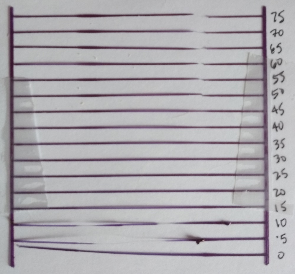
Edit: Not what I expected. 0 at right working to left with Linear Advance increased by 5 at each divider. Print speeds all set to 100mms, with 200mm width and 0.5mm walls. Acceleration set to 0 for all settings.

The corners tightened up near 30, but those bands got worse. I stopped it too soon perhaps, may have been improving above 40. @vintagepc, I think the alternating patters are the result of changes in print direction as you suggested. The holes are on the other side.
This is with TonerPlastics PLA that was on sale cheap for Black Friday last year.
Thanks for the suggestions.
and miscellaneous other tech projects
He is intelligent, but not experienced. His pattern indicates two dimensional thinking. -- Spock in Star Trek: The Wrath of Khan Unfortunately,…
Re: IN SEARCH OF: Meaningful Linear Advance Calibration
Based on the slight elephant footing on one end, bottom of your print is on the right end of your pict.
Nozzle travel direction during printing is upward in picture.
Shouldn't we be examining the other, undisplayed, end of the long tower face for LA effects. That should be the end of the long motion. The corner in the picture is at end of shortest motion segment rather than end of the long segment.
Course, I could have it all upside down. Which was is bottom of tower?
Re: IN SEARCH OF: Meaningful Linear Advance Calibration
[...] Course, I could have it all upside down. Which was is bottom of tower?
Sorry, 0 at right is the bottom. It did warp a bit, so the elephant's foot is exaggerated. I believe direction of travel alternated with the hold on one side.
This thing is awkward to photograph being 200mm long. I'll try for some pics that capture all the layers at different points. Using 0.5mm walls, the upper layers are a bit wobbly. I have a 1.5mm walled version but was thinking that might mask issues.
Let me see if I can get some better daylight pics.
and miscellaneous other tech projects
He is intelligent, but not experienced. His pattern indicates two dimensional thinking. -- Spock in Star Trek: The Wrath of Khan Unfortunately,…
Re: IN SEARCH OF: Meaningful Linear Advance Calibration
I don't recall ever seeing perimeters being laid down clockwise (viewed from top).
I always see the nozzle traveling counter-clockwise. Even with the hole, wouldn't that make it two, separate counterclockwise perimeters - nozzle always going left to right when viewed facing vertical surface being printed.
Re: IN SEARCH OF: Meaningful Linear Advance Calibration
I checked it out with gcode.ws, and the 0.5mm wall extrusions do reverse directions when they hit the hole, at least if I'm interpreting the tiny display properly. Of course, I'm not sure what Slic3rPE is doing without having to watch the print.
I wish Slic3rPE still had the 2D view to look at full screen!
and miscellaneous other tech projects
He is intelligent, but not experienced. His pattern indicates two dimensional thinking. -- Spock in Star Trek: The Wrath of Khan Unfortunately,…
Re: IN SEARCH OF: Meaningful Linear Advance Calibration
Yes, but the reverse direction is on the opposite side of the object. Still ends up going left to right relative to object face being printed despite reversal in absolute global coordinates.
Re: IN SEARCH OF: Meaningful Linear Advance Calibration
Hmm. Just to make sure we're talking about the same thing, here's the gcode animated in Simplify3D. Notice the extruder reversing direction in the rounded corer at about the 0:40, and again at about the 1:45 mark. It's a 0.5mm wall, so is being printed in a single extrusion. It's a bit wobbly, so I'm considering thicker walls, but thought the effect would be more apparent at 0.5mm wall thickness.
Yes, but the reverse direction is on the opposite side of the object. Still ends up going left to right relative to object face being printed despite reversal in absolute global coordinates.
Edit: Here's (hopefully) a better overview. Around the 0:25 and 1:40 mark the extruder reverses direction.
Good chance I'm being thick about this, so apologies if I've missed the mark.
and miscellaneous other tech projects
He is intelligent, but not experienced. His pattern indicates two dimensional thinking. -- Spock in Star Trek: The Wrath of Khan Unfortunately,…
Re: IN SEARCH OF: Meaningful Linear Advance Calibration
This might help. Thor and Loki are looking at an object being printed between them. The red arrows clearly show the direction of the print head reverses.
Neither Loki or Thor have x-ray vision (Marvel not DC). They can only see the wall nearest them. From each ones perspective, the wall being printed is ALWAYS from left to right. So, the end of the travel is always at the right side of the object wall when you look directly at the object.
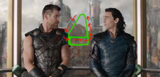
That is why I keep wanting to see the right side of the longes walls. That is where the LA effects should be most clear. The left edges are after smallest distance and are also distorted by angle change ringing.
Re: IN SEARCH OF: Meaningful Linear Advance Calibration
[...] That is why I keep wanting to see the right side of the longes walls. That is where the LA effects should be most clear. The left edges are after smallest distance and are also distorted by angle change ringing.
Ah, sorry. Thought you wanted to ensure the print direction changed. Here are some pics of the corners. I numbered 1 along the front Z axis, 2 to the right (curved corner), 3 on the rear, 4 on the left as viewed from the front:
Face 1-2:

Face 2-3:

Face 3-4:

Face 4-1:

Unfortunately the part is large enough to be cumbersome to fit into my little lighting stand.
I suspect you want to see that right-most front wall squared off. Will generate some squared off prints.
and miscellaneous other tech projects
He is intelligent, but not experienced. His pattern indicates two dimensional thinking. -- Spock in Star Trek: The Wrath of Khan Unfortunately,…
Re: IN SEARCH OF: Meaningful Linear Advance Calibration
Yes. Definitely interested in closer view face 3 at edge 3/4
That is where I would be looking for changes.
Re: IN SEARCH OF: Meaningful Linear Advance Calibration
Yes. Definitely interested in closer view face 3 at edge 3/4
Here's are close-ups in good light:


LA 0 is at left, 45 on right. I'll do my next prints in black or silver.
and miscellaneous other tech projects
He is intelligent, but not experienced. His pattern indicates two dimensional thinking. -- Spock in Star Trek: The Wrath of Khan Unfortunately,…
Re: IN SEARCH OF: Meaningful Linear Advance Calibration
I gotta agree with your assessment. There is amazingly little visible effect as you varied LA.
Re: IN SEARCH OF: Meaningful Linear Advance Calibration
I gotta agree with your assessment. There is amazingly little visible effect as you varied LA.
I may have figure out part of what's going on. Hollow prints always print external perimeters at slow speed, regardless of speed or linear advance settings:

The same part printed as a solid prints at specified speeds:

That's the old XYZ cube magnified to 400% and cut off at 20mm. At smaller than 80mm, the extruder doesn't come up near maximum specified speeds (100mm).
Half the fun testing is developing good benchmarks. I'm hoping an 80mm solid cube will work. Printing now. Hopefully I can get it down to a more reasonable quick print. I think I need to print my towers as solids going forward. Will update soon.
Lesson 2: Don't buy 3Kg of untested filament, even at good Black Friday sale prices. This TonerPlastics stuff is not even 1.65mm. Burning through it until I get test pieces that show something, then I'll go back to glossy black or silver.
and miscellaneous other tech projects
He is intelligent, but not experienced. His pattern indicates two dimensional thinking. -- Spock in Star Trek: The Wrath of Khan Unfortunately,…
Re: IN SEARCH OF: Meaningful Linear Advance Calibration
According to this test, Linear Advance only provides correction at start and stop regions of motion. Also it seems it is happening when the printer is accelerating and decelerating. I wouldn't look for effects on long strokes.