Einsy-Rambo 1.2e Exploded component
Hi I'm looking for some help, I don't know enough about electronics to go on.
Context my mk3s+ printer with a bear mod, recently stopped working (can be turned on throws a warning that the left fan does not turn on).
After analyzing why it was happening I found this on the PCB:
Some looking around, I found this: https://github.com/ultimachine/Einsy-Rambo/tree/1.2e/board/Project%20Outputs
After comparing images I have understood that this is the affected area according to the schematics/diagrams or whatever:

And I don't understand much but I assume this is the circuit:
On the basis of all this I ask my doubts:
1-Why is this happening, do you know?
2-Do you think it is repairable, I mean can I bypass to continue passing the signal or replacing the component?
3-Which component is the one that has exploded based on the images, in case I have to replace it?
4-I should make other checks, before trying to repair it, apparently it is the only thing that is damaged?
5-According to the diagram I understand that the component would be in the blank space below C124 next to R30 & R34 but as there is no clear number I don't know what it is.
Any help is appreciated
It's an electrolytic capacitor. If you have the correct diagrams it's the 100nf C124
Most often electrolytics fail with a gentle bulge on the top and then replacement often fixes the issue. Catastrophic failure is unusual and often means that something else failed first and overloaded it - however capacitors are cheap and this one is big enough to solder by hand so replacing it will be a fairly easy attempt at a fix. Make a careful note of the orientation of the failed component when you remove it - the leads may be marked '+' and/or '-' and there is usually some sort of stripe next to the '-' lead; the new part MUST be fitted the same way around.
This one appears to be across a fan motor supply, check the fan is in good order, clean and turning freely; the damage might have been caused by a stalled fan or a failed motor winding.
Cheerio,
RE: Einsy-Rambo 1.2e Exploded component
No, C124 is right there on the board, alive and well. It is not an electrolytic capacitor but a small multilayer SMD cap -- it's only 100 nF after all.
Looks more like FB40 blew up, a ferrite bead. It is connected in series with the fan on connector J5. Can you measure whether the fan has shorted out? (Multimeter between pins 1 and 2 of J5. Measure in Ohm mode with the printer power off.)
Oops! Thanks for catching that. I completely misread the scale of the image and didn't check.
Cheerio,
RE: Einsy-Rambo 1.2e Exploded component
Darn. That is terrible.
--------------------
Chuck H
3D Printer Review Blog
Yes. Worse, I've just done a blown capacitor replacement on a monitor which looked a lot like that - but ten times larger - somehow despite that I didn't notice the scale so relied on a cursory glance and then to compound it read nano as micro. Luckily @jurgen-7 spotted the error before any damage could be done. One of the advantages of the forum system is that others are watching.
Cheerio,
RE: Einsy-Rambo 1.2e Exploded component
First of all thank you all for your time and patience.
Sorry for my ignorance in all this, I have taken a picture orienting the pin as the digram.
No, C124 is right there on the board, alive and well. It is not an electrolytic capacitor but a small multilayer SMD cap -- it's only 100 nF after all.
Looks more like FB40 blew up, a ferrite bead. It is connected in series with the fan on connector J5. Can you measure whether the fan has shorted out? (Multimeter between pins 1 and 2 of J5. Measure in Ohm mode with the printer power off.)
Which would be 1 and 2?
The square and the circular one in the middle?
Or the 2 circular ones (I understand that if it is like this it is as seen in reverse).
RE: Einsy-Rambo 1.2e Exploded component
Which would be 1 and 2?
The square and the circular one in the middle?
Or the 2 circular ones (I understand that if it is like this it is as seen in reverse).
Pin 1 is the rectangular pad, and pin 2 is next to it (the center pin).
RE: Einsy-Rambo 1.2e Exploded component
Okay, according to the following image.
I measured using a tester at 200Ω, and by “nothing” I mean that there was no continuity/tester gave 1.
Between point 1 and point 5 nothing (Pin 1 and Pin 2)
Between point 1 and point 2 it gave 0.05
Between point 2 and point 3 nothing
Between point 3 and point 4 nothing (Should I assume the component is also dead?¿)
Between point 4 and point 5 gave 0.05
RE: Einsy-Rambo 1.2e Exploded component
With a burnt circuit board, the charring on the board can give you a short or resistance reading. You need to clean the board before doing any resistance tests. Clearing the charring will also make it easier to see the fault.
RE: Einsy-Rambo 1.2e Exploded component
All your readings except for the first one (pin 1 to pin 2) are as expected:
There are PCB traces between points 1-2 and point 4-5, so these should be connected.
The ferrite bead that belongs between points 2-3 has burnt out, so there is an open circuit now.
Capacitors do not conduct DC, hence C124 between points 3-4 measures as an open circuit.
The fact that the fan (points 1-5, pins 1-2 of the connector) measures as an open circuit is surprising. I would have expected some DC resistance, but well above zero Ohm. Could you measure again using a higher range of your meter, e.g. 20 kOhm? Could you also measure between the corresponding pins on the FAN1 connector (J4) for comparison? Also, polarity may matter for this measurement -- put the positive (red) lead of your meter onto the center connector, the ground (black) onto the rectangular pad.
What we are aiming to do is to figure out why ferrite bead FB40 has burnt out. The bead itself is just a passive component -- essentially a piece of wire with ferrite material around it. You will see many of these ferrite beads (FBxx) in the schematic diagram, on most of the connectors to off-board wiring. They are meant to suppress unwanted radio emissions, stemming from the high-frequency clock signals on the board.
You could just replace the burnt-out ferrite bead with a wire jumper, but some other component would likely fail right away then, since something is causing an overload. The fan is a likely culprit here.
One more question: You mentioned in the original post that the board works, except for the fan. Could you provoke a situation where the fan needs to turn on and off, and observe whether LED5 (red LED) goes on and off then?
RE: Einsy-Rambo 1.2e Exploded component
With a burnt circuit board, the charring on the board can give you a short or resistance reading. You need to clean the board before doing any resistance tests. Clearing the charring will also make it easier to see the fault.
Any tip, or reference video about how to do it without damaging(more) the PCB?
The fact that the fan (points 1-5, pins 1-2 of the connector) measures as an open circuit is surprising. I would have expected some DC resistance, but well above zero Ohm. Could you measure again using a higher range of your meter, e.g. 20 kOhm? Could you also measure between the corresponding pins on the FAN1 connector (J4) for comparison? Also, polarity may matter for this measurement -- put the positive (red) lead of your meter onto the center connector, the ground (black) onto the rectangular pad.
Hmmm, something strange, I have tried 20k on both (FAN0 & FAN1) and both read 1 on the multimeter.
Could it be that I'm reading the pins wrong and they are seen with the board upside down (the 2 circular ones). I prefer to ask before I do this in case I damage something else.
You could just replace the burnt-out ferrite bead with a wire jumper, but some other component would likely fail right away then, since something is causing an overload. The fan is a likely culprit here.
One more question: You mentioned in the original post that the board works, except for the fan. Could you provoke a situation where the fan needs to turn on and off, and observe whether LED5 (red LED) goes on and off then?
Well, the ''funny'' part of this, is that I have not only 1, but 2 PCB's with the same problem.
I am not 100% sure if it was the same printer that damaged both boards, but I am pretty sure it is the same “hardware” that damaged the PCB.Right now I have the culprit with the second PCB broken. Which has the same problem. ASAP I'll make a video or something.
I assume that it could be the fan that is the cause.
The strange thing is that after changing the first PCB the printer worked for several days/months without problems.
RE:
One more question: You mentioned in the original post that the board works, except for the fan. Could you provoke a situation where the fan needs to turn on and off, and observe whether LED5 (red LED) goes on and off then?
Okay, it go on an then off when power on the printer (normally both fan spin during some second/s but now just the print fan spin).
And when I put as preheat (PLA), it on again around 50ºC and then next to 100ºC the printer throw error and stop heating and while temp is over 50ºC it keep light ON.
I tested it with “PCB 2”, which is still connected but the behavior is the same as I had with “PCB 1” back in the past.
Also say that the “PCB 2” has not “exploded so much”, it is rather burned.
Edit:
I prefer to first try to try/experiment with “PCB1” because it is the worst (in my opinion), and if I get the experience of how to fix PCB1 it will seem easier to repair PCB2.
RE: Einsy-Rambo 1.2e Exploded component
I don't think you need to do much cleanup. If the ferrite bead is burnt up, it is electrically "out of the circuit". You can replace it with a wire that you solder to the adjacent components: Connect pin 1 of J5 to that side of C124 which is pointing towards FB40. That's better than trying to solder to the charred traces on the PCB, which might come loose quite easily after having overheated.
The pin numbers on connectors J4 and J5 will always be: Pin 1 = rectangular pad, pin 2 next to it (center pad), pin 3 on the far side. It doesn't matter which side of the PCB you are looking at.
Good to read that the LED is turning on and off as it should. So the switching transistor, Q2A and Q2B, is still doing its job and did not incur damage.
If the printer has already killed two boards, I would replace the fan (FAN0, apparently the left one in the printer?) even without further diagnosis. Not sure why you can't measure some internal resistance in the fans -- if they have internal electronics, maybe the voltage from the multimeter is not enough to measure them? If you have an external 5V power supply, you could unplug the fan and try to drive it from that supply (5V on pin 2, GND on pin 1), and maybe measure the current it takes. But you can also just buy a new fan and give that a try.
RE: Einsy-Rambo 1.2e Exploded component
Not sure why you can't measure some internal resistance in the fans -- if they have internal electronics, maybe the voltage from the multimeter is not enough to measure them?
Wait you mean the fan itself or the pins where fan is connected, I only check the pins where fan is connected, not the fan.
I will check tomorrow and say something.
I don't think you need to do much cleanup. If the ferrite bead is burnt up, it is electrically "out of the circuit". You can replace it with a wire that you solder to the adjacent components: Connect pin 1 of J5 to that side of C124 which is pointing towards FB40. That's better than trying to solder to the charred traces on the PCB, which might come loose quite easily after having overheated.
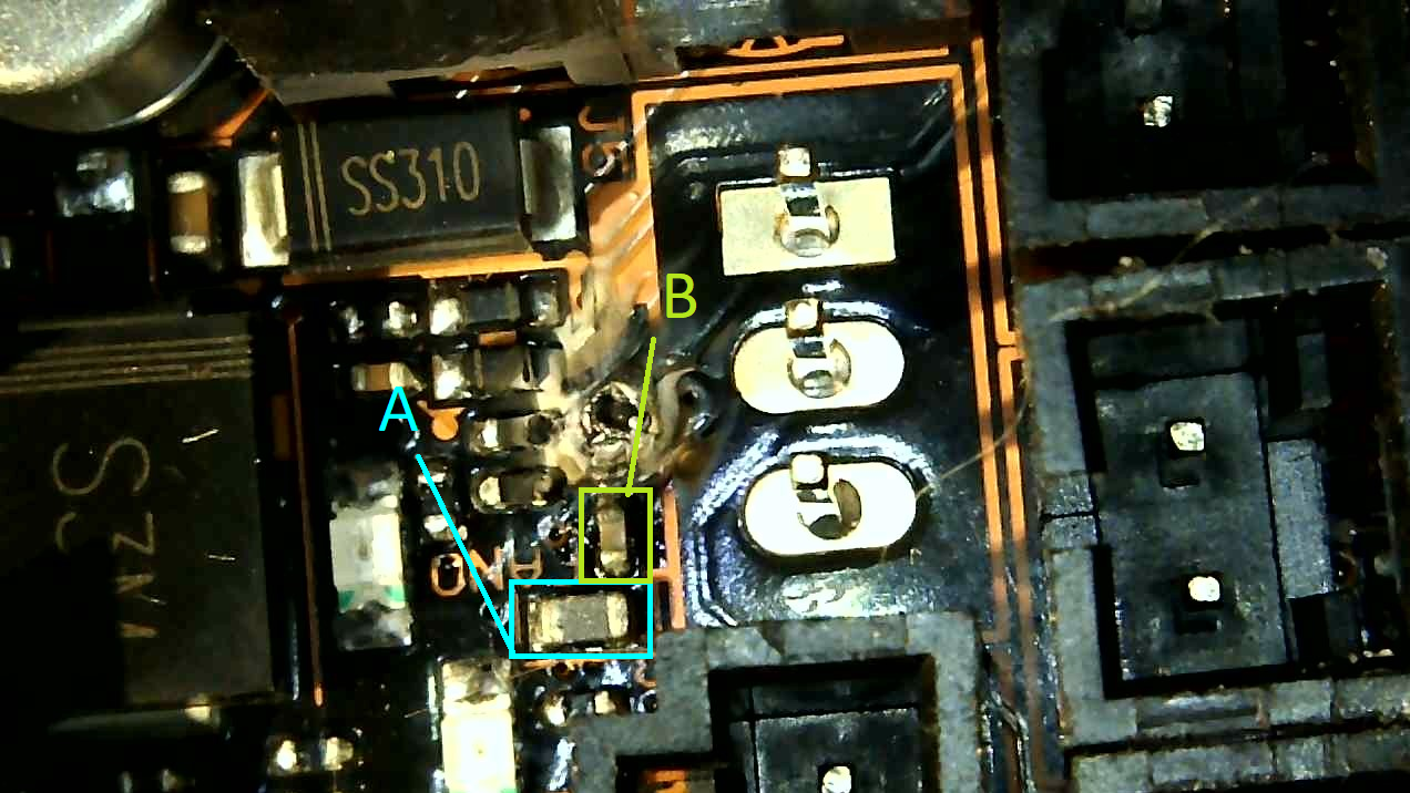
Just to be clear C124 is B right? and even if it does mark as open circuit if I connect the side closest to PIN 1 with PIN 1, it may be works.
RE: Einsy-Rambo 1.2e Exploded component
Yes, that's right -- the component you have marked with "B" is C124. Capacitor C124 is normally connected to pin 1 of J5 via the ferrite bead (which has now burnt out). Hence a wire will reconnect it (from the C124 pin which is closest to pin 1).
The fan resistance measurement is meant to test the internal resistance in the fan. You can either measure at the PCB contacts (while the fan is plugged in, of course); or you can disconnect the fan and measure directly at its plug.
One detail I find puzzling is how connector J5 is soldered in. It has nothing to do with the failure, most likely, but I am curious: Various photos of the Einsy board which I found online show it with the fan connectors on the top side -- but yours seems to have the connectors on the bottom, with the pins sticking out on top. Is that how it came from the factory?
Also, if the J5 pins are soldered from the top side, I would expect to see solder on those pads and pins. (The typical concave "pyramids" of solder, wetting the pad and the bottom part of the pin.) There is no solder visible in your closeup photos -- maybe there is a small amount inside the through-holes. Are those three pins properly soldered? Do all the connectors look like this? It would be great if you could post photos which show to entire board, from the top and bottom.
RE: Einsy-Rambo 1.2e Exploded component
Yes, that's right -- the component you have marked with "B" is C124. Capacitor C124 is normally connected to pin 1 of J5 via the ferrite bead (which has now burnt out). Hence a wire will reconnect it (from the C124 pin which is closest to pin 1).
Okay I'm going to try to bridge it, any type of wire I should use or specific AWG?
The fan resistance measurement is meant to test the internal resistance in the fan. You can either measure at the PCB contacts (while the fan is plugged in, of course); or you can disconnect the fan and measure directly at its plug.
Ok I think the fan is almost dead, at 20 kOhm it marks as open(Also if I use 2MOhm). If I use the FAN1(the print fan) to measure it gives a 3.3-3.4 using 20 kOhm.
The funny part is that if I put the FAN0 connected to the FAN1 pin of the PCB this fan turns on (I guess it can run with more power, but that's why ferrite bead component exploded by overload).
One detail I find puzzling is how connector J5 is soldered in. It has nothing to do with the failure, most likely, but I am curious: Various photos of the Einsy board which I found online show it with the fan connectors on the top side -- but yours seems to have the connectors on the bottom, with the pins sticking out on top. Is that how it came from the factory?
Also, if the J5 pins are soldered from the top side, I would expect to see solder on those pads and pins. (The typical concave "pyramids" of solder, wetting the pad and the bottom part of the pin.) There is no solder visible in your closeup photos -- maybe there is a small amount inside the through-holes. Are those three pins properly soldered? Do all the connectors look like this? It would be great if you could post photos which show to entire board, from the top and bottom.
I don't quite understand what you mean, they are welded on the back, that's the usual, right?

RE: Einsy-Rambo 1.2e Exploded component
I don't quite understand what you mean, they are welded on the back, that's the usual, right?
Aha, they are just bare individual pins, and what we were looking at is actually the connector side! Unusual; normally one uses pin strips which are held together by a plastic strip, or a shroud with a notch which also serves to enforce the right polarity.
Not a cause for concern. But since the connector does not define the polarity, are you sure that you always plugged in the fans the right way round? (Are both fans the same type, with the same color-coding of the wires?)
Okay I'm going to try to bridge it, any type of wire I should use or specific AWG?
That should not be critical. I would use a single-strand wire which is stiff enough to keep its shape. No insulation needed then; just bend it the way you need it, making sure that it does not touch any unwanted contacts. (It can touch the former FB40 terminals, since it's bridging those anyway.) A clipped-off piece of resistor lead would work nicely for example.
RE: Einsy-Rambo 1.2e Exploded component
Aha, they are just bare individual pins, and what we were looking at is actually the connector side! Unusual; normally one uses pin strips which are held together by a plastic strip, or a shroud with a notch which also serves to enforce the right polarity.
Not a cause for concern. But since the connector does not define the polarity, are you sure that you always plugged in the fans the right way round? (Are both fans the same type, with the same color-coding of the wires?)
I assume you are referring to these pieces that are put on the PCB pins to know how they should be connected.
RE: Einsy-Rambo 1.2e Exploded component
Jürgen is doing a good job of helping you. I would use a single strand of wire. It will help protect other parts of the circuit if the fan is damaged and you don't replace it.
A fan running for a short period of time may not be enough to burn out the circuit. There may also be an intermittent issue with the fan that can draw lots of current. A cable that has insulation damaged could cause an intermittent short circuit which would cause the issue. Heating will cause things to expand and that cause a low resistance. Problems like this are a bane to electronics techs. You think you fixed something and it still goes pop when you least expect it.
Where the ferrite core is located, the only things that can cause it to heat up and be damaged are the fan or cables to the fan.