Where can I find someone to design this for me?
I am not brand new
but still learning and now I am
stuck, I have been trying to design this for a month now (off and on) and for some reason I can seem to figure it out.. I know it should be simple but I am having creators block...
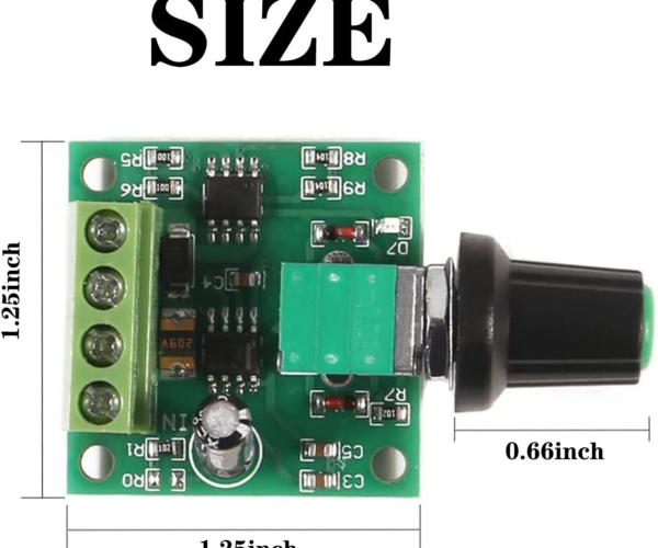
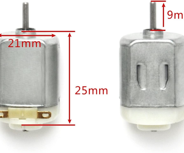
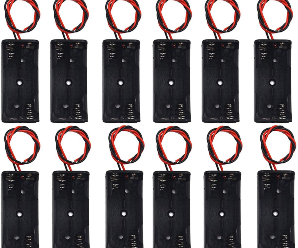
I need this to rotate the top using the motor, speed controller and battery pack (see attached photos) which should all be located in the bottom base...
Would prefer it to not have a lot of parts as this should be printed a lot.
I have tried several options and cant get it right.
I am willing to pay (a reasonable amount) for a working piece... again doesn't have to be complicated, would prefer to keep it as few moving parts as possible...
Any Suggestions??
RE: Where can I find someone to design this for me?
Could you do a quick and dirty hand sketch of how you think all of the parts should fit together? Just looking at the dimensions it would appear that the bottom will have to be much taller than the drawing suggests to be able to fit the motor in vertically plus there is no height info on the control board which may or may not have to fit under the motor. What are the parts at the shown bottom?
It doesn't look like it will be that hard but I am having a lot of difficulty visualizing it.
jwv
This is the sort of design that often goes through a surprising number of iterations and once operating goes through more test and refine cycles. It isn't easy, so don't despair.
Some observations and questions:
The measurements appear to be a mix of metric and imperial - always a potential source of issues.
The control knob you have chosen doesn't allow clearance for the case.
The motors are not geared, is the top intended to spin at very high speeds? If so the weight distribution of the top MUST be balanced somehow to prevent vibration.
Does the top bear any weight? There seems to be no provision for a thrust bearing.
How are the motors to be mounted?
How are the motors to drive the top.
How is the top connected?
And have you made a mock-up or prototype to check the underlying assumptions?
Cheerio,
RE: Where can I find someone to design this for me?
I have tried several different configurations but just cant seem to get it right...
I make litho lamps.... the first image I posted is one that will rotate to show all four litho's but you have to do it manually. I am trying to make it so you can just turn the knob and it will rotate for you...
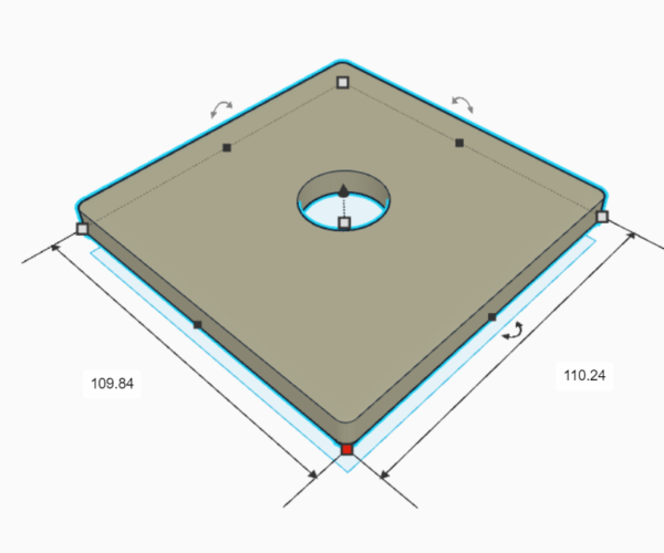
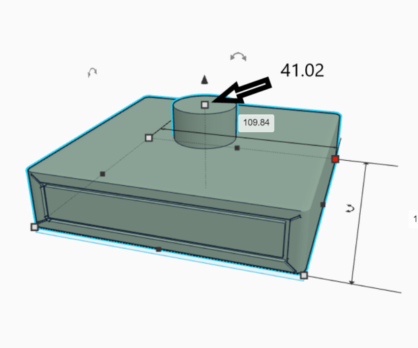
These two are the closest I have come to getting it right....
RE: Where can I find someone to design this for me?
Diem,
Here are the answers to your questions...
The measurements appear to be a mix of metric and imperial - always a potential source of issues. I just took the photos of the items I purchased from amazon to get the measurements, I convert everything to metric
The control knob you have chosen doesn't allow clearance for the case. Once it is inserted into the case, it allows me to place the Knob on the controller..I didnt want to have a huge hole in the side
The motors are not geared, is the top intended to spin at very high speeds? If so the weight distribution of the top MUST be balanced somehow to prevent vibration. for the first design (in the photos) the motor would fit into the "funnel" and be either glued or locked into place, the second photo has a gear that will fit on the end of the motor
Does the top bear any weight? There seems to be no provision for a thrust bearing. Yes, there will be a litho box on the rotating platform or the actual litho box will be the platform... doesnt bear too much weight as the lithos are only 88mm x 88mm x 2mm. but it does bear weight
How are the motors to be mounted? First design, the motor fits very tightly into the "clamp" vertically.. Second photo, the motor will be placed on the "holder" vertically and then probably zip tied to it.
How are the motors to drive the top. Please see the photos for attachments
How is the top connected? the lid should fit over the top of the base snug... it has to be removed to change batteries
And have you made a mock-up or prototype to check the underlying assumptions? yes, I have printed probably 15 prototypes ..all failures.... my assumption is, "I cant Design this" lol...
RE: Where can I find someone to design this for me?
I agree with everything Diem said adding that there critical dimensions missing and the gear train does not seem like it will work. Also it looks like you might be trying to do the design with TinkerCAD and while it may be possible, it will be really hard. I happen to like FreeCAD which is an opensource, free, piece of software. Of all the modules, you need to learn Part Design, Sketcher, perhaps a little bit of Part and last, Mesh Design which is the piece that converts your file to STL for import into a slicer.
The image below is a rough cut I did with a lot of guessing on different dimensions. I am also attaching a zip with more views and the FreeCAD file to give you a starting point. Search for FreeCAD install and you should find the download easily.
jwv
RE: Where can I find someone to design this for me?
Rather than design a gearbox and calculate printable involutes I suggest you consider geared motors. With something around 1000:1 your speed control will be simpler and probably more linear. As this is a display unit I presume you are planning around 1-2 rpm..?
You still need some sort of bearing to support the rotor but at those speeds balance is not so critical.
Where will you place the lanp and how are you planning to route power to the lamp?
the lid should fit over the top of the base snug... it has to be removed to change batteries
So effectively everything has to mounted to the lid to avoid excessive disassembly at battery change.
I have printed probably 15 prototypes
I meant before trying to print the whole unit. What is the rotor anticipated to weigh, what speeds do you get from the motor and controller, how much power does it consume at anticipated loads, how many & what size batteries are required for the planned change frequency?
Have you considered: at low DC power mains converters (wall warts) are another option, thus eliminating battery changes and simplifying the internal layout?
Even a cardboard and tape prototype would help address some of these issues.
Cheerio,
RE:
@russell38320 Where do your designs fail ?
Have you considered using a geneva mechanism for synchronization ?
Having problems with bed adhesion every morning...
