Re: Scarring on top surface
The STL looks fine to me: and definitely no seams on the top surface in my slice. I'm back to something mechanical...
Untitled.jpg
Most bizarre. I can't see a mechanical problem with the printer causing that regular a pattern. I'd offer to try and print the STL on my printer for comparison, but I'm headed out of town for a business trip on Sunday and currently have a 0.25mm nozzle in my printer with a print that will finish sometime mid-day tomorrow. If you haven't solved it by next weekend, I'll be happy to give it a shot.
Re: Scarring on top surface
I'm thinking a dimple on one of the rods causing a rattle in one of the planes. But I'm reaching. I'd be curious if the 'seam' will change direction if the part is rotated 90.
Re: Scarring on top surface
The pattern doesn't seem to be consistent (and the near perfection of the LCD cover and the demo PRUSA print make me think it's a slicing thing or zhop thing (though it seems too regular for a zhop thing). I'll have to try ramping zlift to something silly for a test just to be sure. Not sure what else to look at.
Re: Scarring on top surface
The top surface (in my slice) is moving at speed the full perimeter to perimeter stroke; and it's not a place for z-hop to even be considered. I have a print in progress ... I'll post a photo in an hour or so.
Seems 200 mm/s infill is too fast for Prusament... some infill underextrusion is happening, plus the surface is pretty dull. But no long "seams" anywhere, but there are a few places where the previous layer shows up, especially where the extruder changed direction of infill, and creates a "visual" line in the top layer. But looking back at the OP image, the 'seam' is exactly where the prior layer has this reversing, too. Hmm.
Re: Scarring on top surface
How very odd. Mine was printed with Polymaker PLA using the Pretty PLA V3 profile at 0.15mm layer height and 20% infill except for one which was printed in the silver stuff that came with the printer (which doesn't seem to behave as well as the polymaker). The second polymaker test was of a lightly revised model (reinforcing two standoffs that I accidentally tore off in the first print) and the third (prusa silver) was of just the flat panel portion (in the interest of speeding up the test). Interestingly, they each show the problem but in different patterns. None of them really look quite like yours, except that all three have some "stripes" that are glossier than others. Photo included for comparison.

The three versions are in order of printing from top to bottom. Interesting how the third one reverses the stripes (though maybe I inadvertently flipped the model when preparing it. I don't remember).
The fact that you're getting the same striping component suggests a not-necessarily-hardware cause, though the lack of the perpendicular "seams" on yours is curious. The closest of mine to yours is #3, which still has perpendicular artifacts, but they seem more little oddly spaced ridges than seams.
Doesn't seem like we have our explanation quite yet, but we're getting there. Thanks for taking the time to do a comparison print on your end.
Correction: My first two prints were pretty PLA at 0.2mm layer height, the third with the Stock Prusa 0.15mm quality profile. All 20% infill.
Re: Scarring on top surface
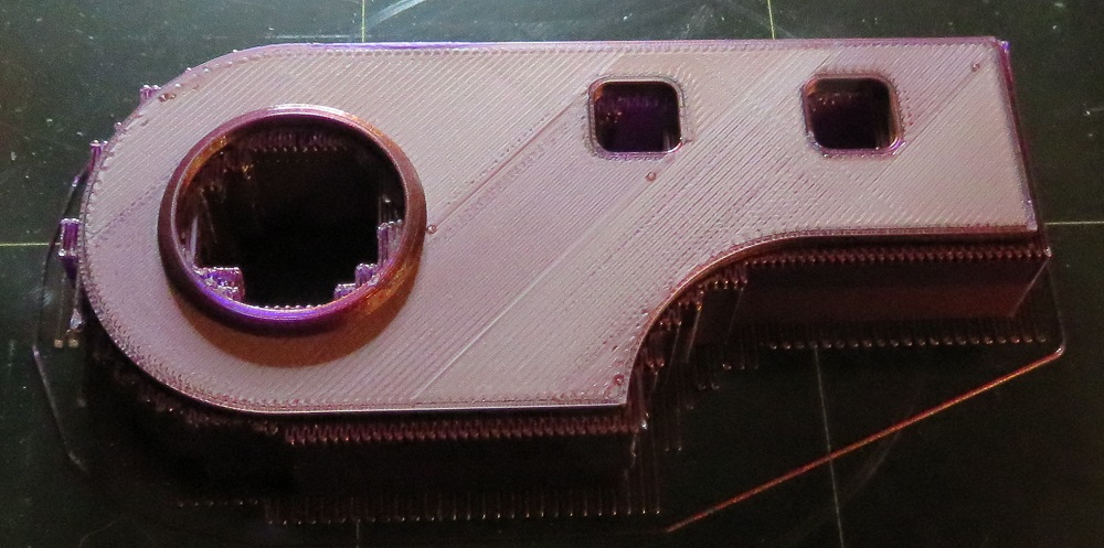
It's all in the infill pattern with the reverse infill layering up at edges of holes. I slowed things down and got this printed surface; it's about as good as I think I could get.

; Filament-specific end gcode

G4 ; wait

M220 S100

M104 S0 ; turn off temperature

M140 S0 ; turn off heatbed

M107 ; turn off fan

G1 Z33.5 ; Move print head up

G1 X0 Y200; home X axis

M84 ; disable motors

; filament used = 1184.2mm (2.8cm3)

; filament used = 3.5

; filament cost = 0.1

; total filament cost = 0.1

; estimated printing time (normal mode) = 21m 6s

; estimated printing time (silent mode) = 21m 9s
; avoid_crossing_perimeters = 0
; bed_shape = 0x0,250x0,250x210,0x210
; bed_temperature = 60
; before_layer_gcode = ;BEFORE_LAYER_CHANGE\nG92 E0.0\n\n;[layer_z]\n;G4 S5 ; G4 P5000 ; pause 5 seconds (5000 milliseconds)\n;{if layer_z == 1}M220 S50{endif} ; layer height @ 1mm set speed 50%\n;{if layer_num == 10}M220 S75{endif} ; layer count @ 10 set speed 75%\n\n; G1 Z11.95:M109 S220:G1 Z6.95 ; multi-command example\n\n
; between_objects_gcode =
; bridge_acceleration = 1000
; bridge_fan_speed = 100
; brim_width = 0
; complete_objects = 0
; cooling = 1
; cooling_tube_length = 5
; cooling_tube_retraction = 91.5
; default_acceleration = 1000
; deretract_speed = 0
; disable_fan_first_layers = 1
; duplicate_distance = 6
; end_filament_gcode = "; Filament-specific end gcode"
; end_gcode = G4 ; wait\nM220 S100\nM104 S0 ; turn off temperature\nM140 S0 ; turn off heatbed\nM107 ; turn off fan\n{if layer_z < max_print_height}G1 Z{z_offset+min(layer_z+30, max_print_height)}{endif} ; Move print head up\nG1 X0 Y200; home X axis\nM84 ; disable motors
; extra_loading_move = -2
; extruder_clearance_height = 20
; extruder_clearance_radius = 20
; extruder_colour = #FFFF00
; extruder_offset = 0x0
; extrusion_axis = E
; extrusion_multiplier = 1
; fan_always_on = 1
; fan_below_layer_time = 100
; filament_colour = #FF3232
; filament_cooling_final_speed = 3.4
; filament_cooling_initial_speed = 2.2
; filament_cooling_moves = 4
; filament_cost = 24.99
; filament_density = 1.24
; filament_diameter = 1.75
; filament_load_time = 0
; filament_loading_speed = 28
; filament_loading_speed_start = 3
; filament_max_volumetric_speed = 15
; filament_minimal_purge_on_wipe_tower = 15
; filament_notes = "Affordable filament for everyday printing in premium quality manufactured in-house by Josef Prusa"
; filament_ramming_parameters = "120 100 6.6 6.8 7.2 7.6 7.9 8.2 8.7 9.4 9.9 10.0| 0.05 6.6 0.45 6.8 0.95 7.8 1.45 8.3 1.95 9.7 2.45 10 2.95 7.6 3.45 7.6 3.95 7.6 4.45 7.6 4.95 7.6"
; filament_soluble = 0
; filament_toolchange_delay = 0
; filament_type = PLA
; filament_unload_time = 0
; filament_unloading_speed = 90
; filament_unloading_speed_start = 100
; first_layer_acceleration = 1000
; first_layer_bed_temperature = 60
; first_layer_extrusion_width = 0.42
; first_layer_speed = 30
; first_layer_temperature = 215
; gcode_comments = 0
; gcode_flavor = marlin
; infill_acceleration = 600
; infill_first = 0
; layer_gcode = ;AFTER_LAYER_CHANGE\n;[layer_z]
; machine_max_acceleration_e = 5000,5000
; machine_max_acceleration_extruding = 1250,1250
; machine_max_acceleration_retracting = 1250,1250
; machine_max_acceleration_x = 1000,960
; machine_max_acceleration_y = 1000,960
; machine_max_acceleration_z = 1000,1000
; machine_max_feedrate_e = 120,120
; machine_max_feedrate_x = 200,100
; machine_max_feedrate_y = 200,100
; machine_max_feedrate_z = 12,12
; machine_max_jerk_e = 1.5,1.5
; machine_max_jerk_x = 8,8
; machine_max_jerk_y = 8,8
; machine_max_jerk_z = 0.4,0.4
; machine_min_extruding_rate = 0,0
; machine_min_travel_rate = 0,0
; max_fan_speed = 100
; max_layer_height = 0.25
; max_print_height = 210
; max_print_speed = 200
; max_volumetric_extrusion_rate_slope_negative = 0
; max_volumetric_extrusion_rate_slope_positive = 0
; max_volumetric_speed = 7.5
; min_fan_speed = 100
; min_layer_height = 0.05
; min_print_speed = 15
; min_skirt_length = 4
; notes =
; nozzle_diameter = 0.4
; only_retract_when_crossing_perimeters = 0
; ooze_prevention = 0
; output_filename_format = {input_filename_base}_{layer_height}mm_{filament_type[0]}_{printer_model}.gcode
; parking_pos_retraction = 92
; perimeter_acceleration = 600
; post_process =
; printer_model = MK3
; printer_notes = Don't remove the following keywords! These keywords are used in the "compatible printer" condition of the print and filament profiles to link the particular print and filament profiles to this printer profile.\nPRINTER_VENDOR_PRUSA3D\nPRINTER_MODEL_MK3\n
; remaining_times = 1
; resolution = 0
; retract_before_travel = 1
; retract_before_wipe = 0%
; retract_layer_change = 1
; retract_length = 0.8
; retract_length_toolchange = 4
; retract_lift = 0.6
; retract_lift_above = 0
; retract_lift_below = 209
; retract_restart_extra = 0
; retract_restart_extra_toolchange = 0
; retract_speed = 35
; silent_mode = 1
; single_extruder_multi_material = 0
; single_extruder_multi_material_priming = 0
; skirt_distance = 2
; skirt_height = 3
; skirts = 1
; slowdown_below_layer_time = 20
; spiral_vase = 0
; standby_temperature_delta = -5
; start_filament_gcode = "M900 K{if printer_notes=~/.*PRINTER_HAS_BOWDEN.*/}200{else}30{endif}; Filament gcode"
; start_gcode = M115 U3.4.0 ; tell printer latest fw version\nM83 ; extruder relative mode\nG28 W ; home all without mesh bed level (cold zero to get PINDA low)\nM104 S185 ; set extruder partial temp \nM190 S[first_layer_bed_temperature] ; wait for bed temp\nM109 S185 ; wait for extruder temp\nM860 S35 ; wait for PINDA temp to stabilize\n; G4 P15000 ; wait another 15 seconds to warm PINDA\nG28 W ; home all without mesh bed level (hot)\nG80 N7; mesh bed leveling using 7x7 array\nG91 ; move relative\nG1 Z10\nM109 S[first_layer_temperature] ; wait for extruder temp\nG1 Z-10\nG90\nG1 Y-3.0 F1000.0 ; go outside print area\nG92 E0.0\nG1 X60.0 E9.0 F1000.0 ; intro line\nG1 X100.0 E12.5 F1000.0 ; intro line\nG92 E0.0\nM221 S{if layer_height==0.05}100{else}95{endif}\n
; temperature = 215
; threads = 20
; toolchange_gcode =
; travel_speed = 180
; use_firmware_retraction = 0
; use_relative_e_distances = 1
; use_volumetric_e = 0
; variable_layer_height = 1
; wipe = 1
; wipe_tower = 1
; wipe_tower_bridging = 10
; wipe_tower_rotation_angle = 0
; wipe_tower_width = 60
; wipe_tower_x = 170
; wipe_tower_y = 125
; wiping_volumes_extruders = 70,70
; wiping_volumes_matrix = 0
; z_offset = 0
; clip_multipart_objects = 1
; dont_support_bridges = 1
; elefant_foot_compensation = 0
; extrusion_width = 0.45
; first_layer_height = 0.2
; infill_only_where_needed = 0
; interface_shells = 0
; layer_height = 0.15
; raft_layers = 0
; seam_position = nearest
; support_material = 0
; support_material_angle = 0
; support_material_auto = 1
; support_material_buildplate_only = 0
; support_material_contact_distance = 0.1
; support_material_enforce_layers = 0
; support_material_extruder = 0
; support_material_extrusion_width = 0.35
; support_material_interface_contact_loops = 0
; support_material_interface_extruder = 0
; support_material_interface_layers = 2
; support_material_interface_spacing = 0.2
; support_material_interface_speed = 100%
; support_material_pattern = rectilinear
; support_material_spacing = 2
; support_material_speed = 45
; support_material_synchronize_layers = 0
; support_material_threshold = 55
; support_material_with_sheath = 0
; support_material_xy_spacing = 50%
; wipe_into_objects = 0
; xy_size_compensation = 0
; bottom_solid_layers = 5
; bridge_angle = 0
; bridge_flow_ratio = 0.8
; bridge_speed = 30
; ensure_vertical_shell_thickness = 1
; external_fill_pattern = rectilinear
; external_perimeter_extrusion_width = 0.45
; external_perimeter_speed = 35
; external_perimeters_first = 0
; extra_perimeters = 0
; fill_angle = 45
; fill_density = 20%
; fill_pattern = grid
; gap_fill_speed = 40
; infill_every_layers = 1
; infill_extruder = 1
; infill_extrusion_width = 0.45
; infill_overlap = 25%
; infill_speed = 100
; overhangs = 0
; perimeter_extruder = 1
; perimeter_extrusion_width = 0.45
; perimeter_speed = 45
; perimeters = 2
; small_perimeter_speed = 25
; solid_infill_below_area = 0
; solid_infill_every_layers = 0
; solid_infill_extruder = 1
; solid_infill_extrusion_width = 0.45
; solid_infill_speed = 100
; thin_walls = 0
; top_infill_extrusion_width = 0.4
; top_solid_infill_speed = 45
; top_solid_layers = 7
; wipe_into_infill = 0
; print_settings_id = 0.15mm OPTIMAL MK3
; filament_settings_id = "Prusament PLA"
; printer_settings_id = Original Prusa i3 MK3 - Anti-Ooze
; printer_model = MK3
; printer_variant = 0.4
; default_print_profile = 0.15mm OPTIMAL MK3
; default_filament_profile = "Prusament PLA"
; compatible_printers_condition_cummulative = "printer_notes=~/.*PRINTER_VENDOR_PRUSA3D.*/ and printer_notes=~/.*PRINTER_MODEL_MK3.*/ and nozzle_diameter[0]==0.4";"! (printer_notes=~/.*PRINTER_VENDOR_PRUSA3D.*/ and printer_notes=~/.*PRINTER_MODEL_MK(2.5|3).*/ and single_extruder_multi_material)"
; inherits_cummulative = ;;"Original Prusa i3 MK3"
Re: Scarring on top surface
Interesting. The Pretty PLA Profile already has most of the speeds as slow as or slower than that, except for max volumetric speed which isn't set, support material at 50, and the acceleration control values.
Re: Scarring on top surface
I have been following this thread and while I do not have any constructive advice to offer to fix, 😳 I have noticed that recently, like since the updates this month and in Dec to the firmware and Slic3r PE, I have noticed my top layers are not as pretty as they had been in the past. No changes to build other than updating the softwares and changing nozzles...
While there will always be texture changes where there is a box or circle like your print has as a result of the way the printer lays filament, it sure seems to be more prominent now than it was in the past if that helps to confirm what you are seeing... it is almost like the top layer is not the top layer if that makes sense...
It seems to me that a setting or two were changed in the build which is causing that appearance, which clearly was not there previously... I wish I could somehow get a way to compare changes in the software/firmware - probably Slic3r PE settings changes to see what could be causing it...
So, it seems to me to be a software change that is causing it, but I am at a loss as to what it is or how to determine.
Strange women, laying in ponds, distributing swords, is hardly a basis for a system of governance!
Re: Scarring on top surface
The important changes are infill acceleration, speed, and max flow limit. These keep sub-layers better controlled, less likely to have artifacts. I also reduced acceleration on the top layer to help constrain any ringing/ghosting from acerbating other problems.
Disclaimer: my test part may not 100% represent because I removed all the posts and support required; though the OP part doesn't show any signs of those structures showing through.
Re: Scarring on top surface
I'm about to do a quick test of turning on "Avoid crossing perimeters" and "Fix STL through Netfab". If that doesn't work, I'll look at speeds (though it would seem suspicious if that was a problem, or others would have noticed, no?). Regarding the fix stl thing: I noticed on a whim that running that seems to get the slice to see it's top and bottom surfaces as parallel and stop slicing on the diagonal (though for this test I've also cut off the standoffs for speed).
Re: Scarring on top surface
I was watching the print closely and I'm pretty sure now that the actual print path is weird (probably gcode). Instead of printing smoothly from one end to the other it is printing in strips, which would seem to correlate to the kind of striping we've seen. It would seem that perhaps the edges between the strips aren't smooth or something. I'm not certain of exactly why we *see* the strips.

Re: Scarring on top surface
This last print looks completely normal. The artifacts from upper left to lower right, are from where the top infill is broken into segments by the geometry of the part. The fainter artifacts from upper right to lower left are from the same thing, but are showing through from the layer below. If you look at the image full size, you can see that the fainter artifacts aren't interruptions of the extrusion, but perturbations of the line. You can also see that they are at exactly 90 degree angles to the top layer and also align themselves with the geometry of the model.
You can play with print settings to help reduce the visibility, but as someone else noted, they will always be there to some degree because of the way the slicer lays top the infill around surface geometry.
Re: Scarring on top surface
Looking back at the earlier pictures, I think all of them are showing the same thing. The yellow filament and lighting just make it look very much like an extrusion start/stop point. Really, I think its just the unevenness of the prior layer, where the infill is split up, showing through on the top layer.
In that case each layer is probably doing the same basic thing as the top, and there's a bit of a ridge in the next as the previous shows through... No idea how to fix it, in any case.
Re: Scarring on top surface
Here's a place the extrusions will be "weird": the slice is filling a layer, hits an obstacle and stops that path. It then has to come from a different direction to complete the fill.
Let's say the slice starts on top: the slice will fill top to bottom, zig-zagging side to side until it hits an obstruction. You'll get to a place where you can't continue. At that point the slice moves to the closest void and continues. If the closest point only has open area above it, it continues upward - opposite the direction it was filling before. if the closest point only has open space below it, the slice continues downward, the same direction it was going before. Where an upwards fill hits a downward fill, you get over extrusion... belt slop and other mechanics makes it worse. I found one weird place where the slice scribbles down and wraps around one of the holes and fills back into a place it just extruder. Pretty wild logic going on.
If this isn't making sense, make a drawing of the part on paper, then try filling it with simple zig-zag lines without lifting your felt pen. You'll have places where you have to lift, go back and fill small places, and places where you can fill up or down the page.
Re: Scarring on top surface
So is the problem basically that the geometry of the part causes the slicer to wig out and do some strange things? Because that's pretty weird and inconvenient. Or perhaps there's some workaround.
Re: Scarring on top surface
Depending upon part symmetry you can sometimes get a better top layer by rotating the part on the build table. That may force a tool path change that may lead to a better result. Or not.
Re: Scarring on top surface
I wonder if Cura's ironing feature would be of benefit (assuming there are no useful settings for Slic3r here), though my attempts to print from Cura have been goey messes for some reason.
Re: Scarring on top surface
You can align the infill with an edge. But when a hole blocks the move, the slicer will start working around it. Not really a defect or bug. The code could be better if it always chose to move a direction, top-bottom, left-right; but turning around seems to lead to thick runs.
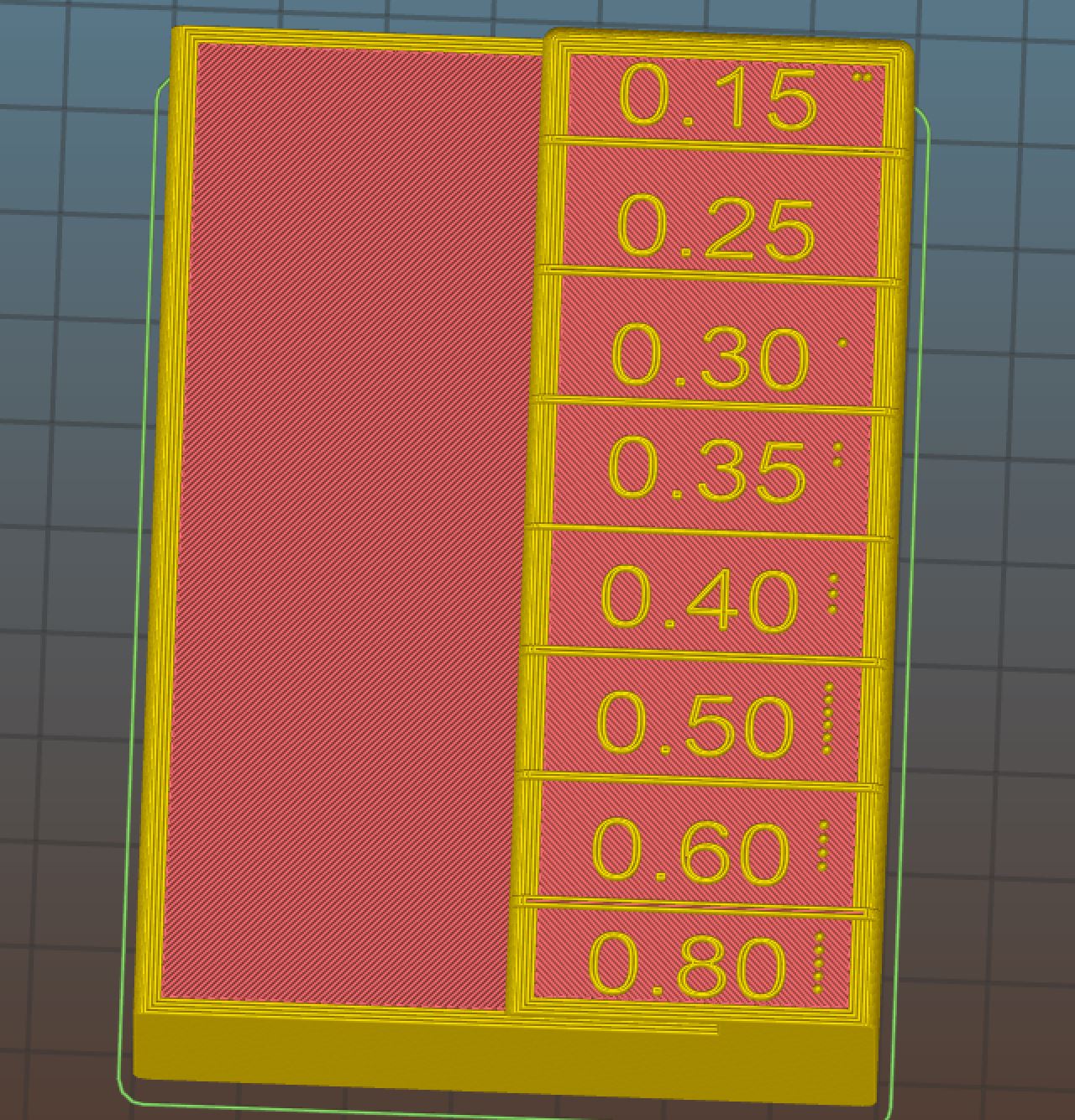
But I was able to reduce this simply slowing down the TOP and SOLID infill print speeds. Slowness is especially helpful for top layers and what's underneath them. 45 mm/s works much better than 200 mm/s.
The trade off is print times go up a bunch. 1h 8m to 1h 16m ... but the top surface quality is a lot better on parts with lots of holes.
Re: Scarring on top surface
I suppose you're right... I'll give it a try with reduced solid/top speeds and we'll see how it goes. At some point I should also try to get Cura behaving for comparison (Cura has an ironing feature which uses the nozzle to smooth out top layers. Not sure if it would really be useful, but might be worth a try).