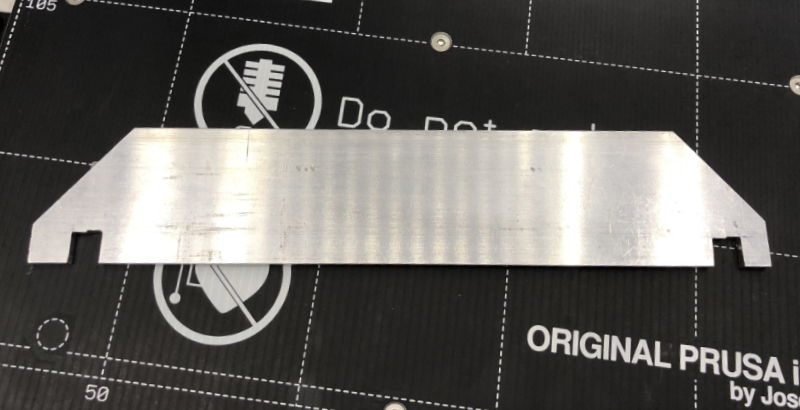
Rod Spacing Jig
Took advantage of having my printer apart to create a rod spacing jig out of aluminum bar stock.
I cut slots to hold rods at a spacing perfectly matched to the distance my bearings hold y-rods apart. Took some careful cutting, filing and scraping, but it's good to 0.02 mm. The slots are slightly tapered so they slip down over rods and engage at largest diameter. The rods then cannot move farther nor nearer.
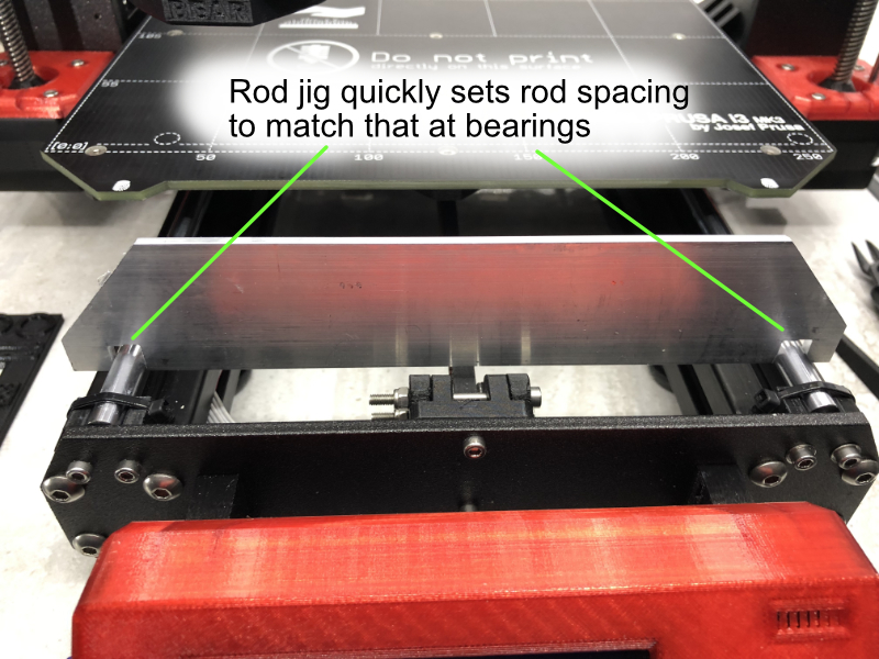
Setting rod spacing is now as fast as the less precise, stock bearing method. I just position the jig over the rods before tightening the right side mounts. Do at front and back. Verify planarity and done. No need to mess with left rod holders because those never get moved once they have been aligned perpendicular with bed x-axis..
Best part is no more removing the top of my enclosure to use my caliper. The caliper was too long to fit inside my enclosure. Also, the jig HOLDS the rods at proper spacing rather than just measuring the distance.
Re: Planar, Parallel and Square
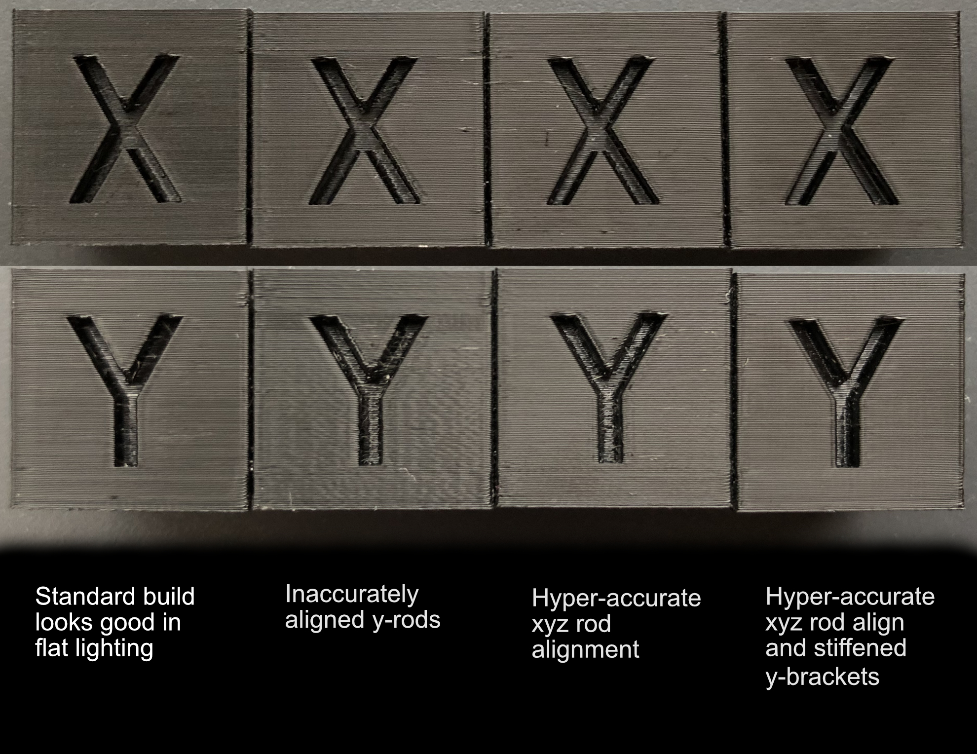
Photographs do not very well show surface finish effects of rod alignment. Once you get decent alignment, the surface finish artifacts are near invisible in flat lighting. Even with shiny, black PETG, it is hard to see the issues.
The below are four BLACK PETG xyz test cubes printed at various degrees of rod alignment. I have placed x-face image above y-faces for corresponding cube.
The leftmost is following standard instructions. It looks pretty good in flat lighting.
The next is with y-rods slightly out of parallel.
Third is after accurate xyz alignment
Finally, is the results after front and rear frame brackets have been stiffened.
You can see how non-parallel Y rods induce their own Y surface noise as the carriage fails to move smoothly. Not all y-axis issues appear on x-axis. If the y-carriage isn't moving well, you can induce waves on the Y surface.
To really see what is happening, you must look at the specular surface reflections. These are best observed with a shiny filament and MOVING the object around to view how light reflects off the surfaces. A still image doesn't represent things well, but the below image shows the same cubes under specular light. Although the surfaces feel smooth, there are small flaws that become apparent.
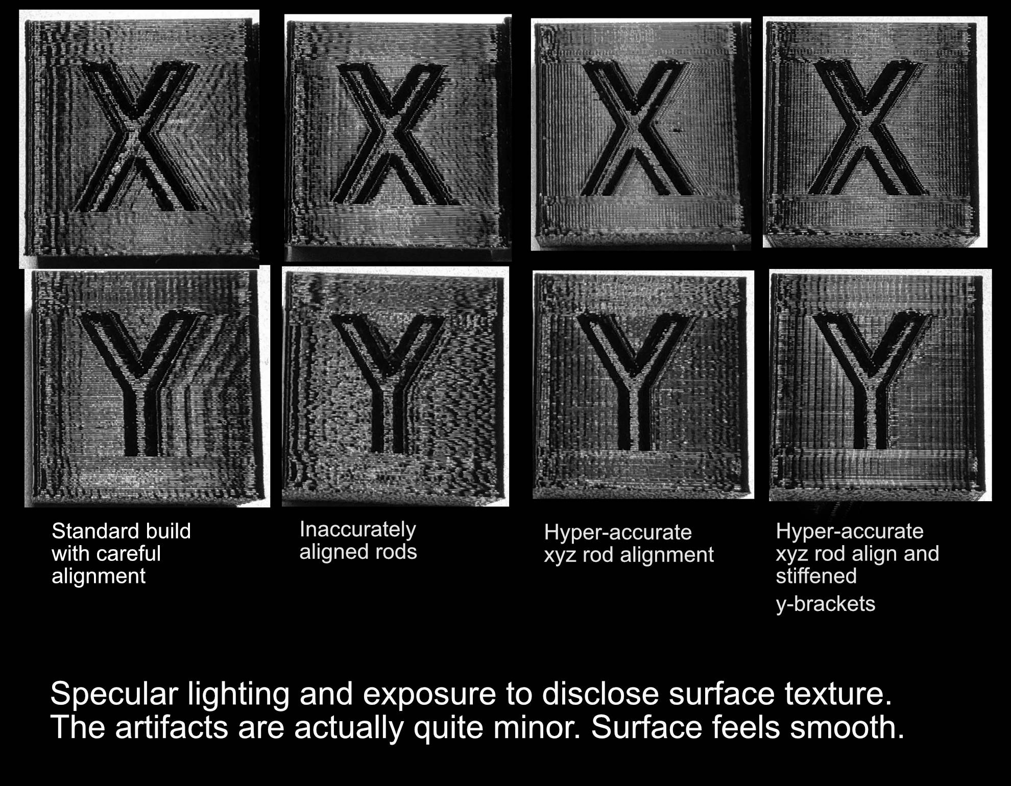
Standard build shows ringing on x and y surfaces. That is the defect that fades out as you go from left to right. Ringing is mostly due to incorrect belt tension and axis slop. Also notice how fine vertical artifacts that go across the entire face are smeared and shift in phase. The smearing and phase irregularity of vertical artifacts are actually sloppiness of the axes hiding a fine, regular noise inherent to our stepper motors.
Second is with accurate x-rods and x-belt. You see less x ringing on x and y-surfaces, mostly due to belt tensions getting correctly adjusted. Also, x-axis motion is more accurate. You see fine vertical artifact getting sharper and in phase on the x-surface. Y-surface is badly smeared left/right by the y-rods being non-parallel.
Third shows what happens when xyz rods are planar, parallel and square. There is now very little left/right smearing of vertical motor artifacts. Ringing is even less now that axis slop is minimized. If you look carefully at the x and y-surface fine artifacts, you will notice it is NOT a sine wave defect as one would see with frame vibration, but rather a sharp impulse that is in phase with motor micro-stepping. The spacing does NOT correspond with 2GT tooth spacing but is related to it by a factor pi. That fine vertical artifact is due to the steppers themselves. Our xyz motion is now high enough precision to reveal stepper artifact. (No it's not the ball bearing motion. Exact same vertical artifact happens with IGUS bushings)
Finally, the fourth cube is with front and back frame brackets reinforced. X-surface has even less y-variation because y-axis is now stiffer. You see the x-surface is overall flatter as evidenced how a narrow portion of the x-surface lights up. The light source is narrow. As the surface gets more flat, the lighted portion gets narrower. Y-axis motion is more precise. Fine vertical artifacts are very sharp and perfectly in phase from one layer to another. Notice how y-surface between vertical artifacts is now super flat.
Hyper-accurate rod alignment visibly increases axis motion precision - even to the point of revealing fine stepper motion artifacts. With "good enough" axis alignment, other artifacts largely swamp out the tiny stepper artifacts. Each stage of noise removal, reveals a smaller underlying noise that was previously hidden.
Re: Planar, Parallel and Square
Proof is certainly in the pudding, enjoying this read. Mine thankfully measured up reasonably well after I finished assembly (0.08deg x to y) and I'm happy to keep it as is for now but this will be helpful down the line if things begin going askew with age. Nice job!
Re: Planar, Parallel and Square
Have you considered selling this work for two or three bucks as a downloadable e-book? It could make you a millionaire faster than you would think. It has happened before. if you have a sense of humor, listen to a podcast called "My Dad Wrote a Porno"
This is exactly what I need to read. Thank you for this.
Re: Planar, Parallel and Square
Thanks. It was a long series of maneuvers that I wanted to document so others might replicate the setup.
You can set up the Mk3 quite accurately - well beyond that achieved via the usual instructions.
Sadly we're currently stuck with TMC2130 tuning issues that no matter how perfectly smooth and precisely we get the axes will still result in vertical artifacts. Until we get access to TMC2130 tuning for each motor, fine vertical artifacts are an inherent mk3 flaw.
Re: Planar, Parallel and Square
Sadly we're currently stuck with TMC2130 tuning issues that no matter how perfectly smooth and precisely we get the axes will still result in vertical artifacts. Until we get access to TMC2130 tuning for each motor, fine vertical artifacts are an inherent mk3 flaw.
I have to correct the above statement. We now know the Vertical Fine Artifacts that become visible once build accuracy is refined enough to remove linear axis mechanical noise. They are NOT due to TMC2130 tuning issues, but rather the non-monotonicity of stock motors.
As of March 2019, VFA's are a completely solved issue if one replaces the motors with better 0.9 degree motors. Unfortunately, 0.9 degree motors require custom firmware.
Re: Planar, Parallel and Square
I'm going to start down this road, though don't know how far I'll go. Also, my MK3S seems to be pretty good as it is, but if small changes can make it better, then good. I have ordered Misumi bearings and rods, though I dread doing the X-axis as the rods were a pain to insert properly....
First a comment about the pieces of glass recommended. My local glass shop wanted $110 for the two, saying that they had to send out to get 3/8" glass cut. But if I wanted 1/4", they could do it in-house for $13! I opted for the 1/4" and it seems quite rigid enough for the purpose (that and I had the pieces within a couple of hours.)
Second, I see people showing the i3 front panel displaying correction offsets, such as you show in https://shop.prusa3d.com/forum/assembly-and-first-prints-troubleshooting-f62/planar-parallel-and-square-t26978-s10.html#p124018 What command does that?
Re: Planar, Parallel and Square
dread doing the X-axis as the rods were a pain to insert properly
Don't dread the X-axis rods. They are super easy to do if you chuck one end into a variable speed drill. Run a rod into each x-end holder hole while keeping the drill spinning. Don't stay in one place, just let it go all the way in and back out. That will prep the rod holes such that the rods smoothly insert but are snug.
Good job on the glass. 1/4 inch should be okay if flat and the price differential is huge.
The offsets can be found in the support menu.
RE: Planar, Parallel and Square
This is a bit of an older thread now, but it is still quite relevant so I wanted to check how well the printer is maintaining its alignment now that you have run it for a while and done significant work with both motors and extruders. Additionally, I was curious as to the particulars of your bearings, rods, and lube. Elsewhere I believe I saw you mention Misumi parts, but was not sure if you went for the looser g6 tolerance PSFJ rods (or similar) or used the h5 PSFU rods that have a snugger fit on their bearings.
RE: Planar, Parallel and Square
After all my motor changes and even replacing the x-axis a few times, the machine has held alignment. It still reports all axes as perpendicular during XYZ calibration.
I went with the G6 Misumi rods. After that is done, the motors become the main culprit for surface finish noise.
RE: Planar, Parallel and Square
@bunny-science
Some years ago I re-modeled my kitchen cabinets using granite tiles. Since these tiles are polished, and because they have to lay down next to each other, they are amazingly flat. So, I drug one out of my spare tile pile and made some measurements.
The "reference" I used is the outside edges of my 12" digital calipers. Flipping it over and repeating measurements showed that this surface is straight (light through the gap between the tile and the caliper is the same flipped either way.
My feeler gauge has gone into hiding for the moment, so I measured the gap between the tile surface and the calipers using the pieces of thin plastic "parts bags". The paper sheets I have around were too thick.
The result of multiple measurements shows that this tile is flat within about 0.05mm (0.002 in), with the center of the tile being "low". In the case of this tile, the center 6 inches or so is flat within my ability to measure, with both edges up about 0.05mm.
So, my suggestion is to find some kind of double sided straightedge and run off to your nearby granite tile supplier (Home Depot in my area), and
- Lay the straightedge on the tile surface
- Put a flashlight on the far side of the straightedge and check out the gap.
- Flip the straightedge over, and repeat.
- Pick the best one you can find and buy it.
These tiles cost about $5 USD in the States.
----------------------------------
One other thought on saving money. The digital calipers don't have to be all that accurate, they only have to be repeatable. Typically you will be making sure two or more measurements are the same. Any digital caliper from ebay or your favorite tool importer should be just fine. Take multiple measurements and average if you have to. Splurge, get a 12" caliper for around $25 - better on sale.
Roger Gault