Planar, Parallel and Square
Planar, Parallel and Square - Introduction
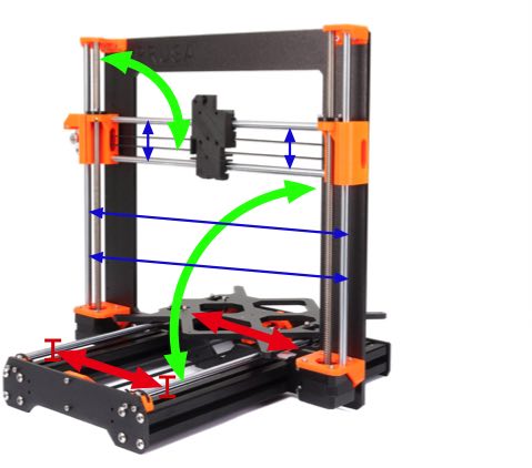
Our Prusa 3d printers rely on linear motion rods in the x, y, z axes. You know that each pair of rods should be parallel to each other and square relative to the other axes, but how far beyond following the build instructions have you gone to optimize rod geometry? This introduces a series on achieving better than normal rod alignment accuracy. I will outline some of the methods I used and invite other forum members to add their techniques as well.
Why Planar and Parallel rather than simply parallel? After all, parallel includes planarity. There is no readily available instrument to directly measure whether two rods are parallel. However, we can test, with reasonable cost equipment, whether two rods are within 20 mics (end vs end) planarity and equidistance. When both of these measurable conditions are met, rods are parallel.
How well we can adjust each axis is limited by the Prusa Mk's design. Although I have replaced most of my stock plastics with ones having better adjustability or stability, these techniques can be applied to the stock plastics.
We'll first cover required materials and tools, discuss pre-requisites and finally work on the axes and print bed.
Progress will be in order of increasing achievable precision...Z axis, X axis, Y axis, Y-carriage and finally the print bed.
CAVEAT: For those who have not already assembled their printer, do NOT attempt these fine tuning adjustments other than the information in the prerequisites section. You should first get your printer built and running to stock specs. This is for after you understand your machine intimately.
Tools and Supplies Needed
Digital Caliper (required) $54
Must be accurate to 0.01 mm and at least 8 inches span. 20 inches would be ideal but probably too costly.
iGaging ABSOLUTE ORIGIN 0-8" Digital Electronic Caliper is accurate at reasonable cost
https://www.amazon.com/gp/product/B00K3PZVKG
Wet or Dry 600 to 800 grit Sandpaper (required)
Required for lapping all plastic mating surfaces flat and perpendicular.
Also required for lapping Y-carriage bushing beds.
Diamond knife sharpening plate (optional)
This is easiest surface for final lapping of plastic parts, but wet, fine sandpaper atop glass flat also works.
3/8 inch thick float glass plate 5" x 8" (required)
3/8 inch thick float glass plate 5" x 16" (optional for Z perpendicularity check)
NOTE: I am shocked at current glass piece pricing ($70/piece). It's MUCH higher than when I got mine years ago.
I'm obtaining a cheaper glass shelf piece to test if it is flat enough
These must be as flat as you can obtain from local glazier. No they won't be perfectly flat, but they are probably the flattest surface as you can reasonably obtain. Have your glazier cut to size and bevel/polish the edges. Obtain several pieces of each size so you can choose the flattest you obtained.
3 mm washers (recommended)
Reduces induced mount motions when bolt heads are tightened against printer frame.
Otherwise, tightening bolt heads can shift carefully positioned plastic parts.
Machinists Square Small (required) $12
https://www.amazon.com/gp/product/B07H7HRKKT
Required to test squareness while lapping surfaces of plastic printer components.
Drafting Triangles (recommended) $8
https://www.amazon.com/Alvin-AS1012-Transparent-Triangle-Set/dp/B00EF1RU0S
Be sure to verify the ones you receive are indeed square. Some plastic triangles are not sufficiently square.
I recommend plastic triangles to avoid marring heated print bed during testing.
You can directly use a large machinist square but they are heavy and easily scratch the heat bed.
Machinists Square Large (optional) $40
https://www.amazon.com/gp/product/B07H7HC5J4
This is good for higher accuracy testing, but if the drafting triangles you receive test as square, you can use those instead.
CD Jewel Case
Commonly available item useful during bed vs x-carriage leveling adjustment
Feeler Gauges
Used during bed vs x-carriage leveling
Jewelers File Set (required) $17
A small, flat file is needed during level X-carriage leveling
https://www.amazon.com/Diamond-Jewelers-Ceramic-Jewelry-10-Piece/dp/B07F1QN224
JB Weld Epoxy (optional)
Used to firmly bed bushings but induce near zero torque and deformation.
Brass Sheets 0.001-0.015 (required) $43
https://www.amazon.com/gp/product/B002BYTCL6
These are required to shim Y-rod positions to better than 20 mics X/Z accuracy.
Also useful for shimming pulley mounts and motors for belt tracking.
Brass Standoff Kit (optional) $19
Female standoffs in this kit are easily ground to make custom length heat bed standoffs
This is a stable, easy bed removal, alternative to springs or nylock fine tuning methods.
USB Microscope (recommended)
This allows higher than visual precision bed XY skew adjustment and measurement of bed/Y-rod alignment.
Obtain one with a removable mounting stand.
Other parts of article series to follow....
Re: Planar, Parallel and Square
....This introduces a series on achieving better than normal rod alignment accuracy. I will outline some of the methods I used and invite other forum members to add their techniques as well....
That's quite an investment required. Maybe you could outline what can be achieved if you make your Prusa printer planar/parallel/square.
Prusa printers are quite forgiving in regards to alignment. I'm looking forward to see how you want to eliminate the tolerance on rods/bearings, frame and plastic parts. If you don't, you might align it but during printing, everything is moving and all the geometry is moving too.
Often linked posts:
Going small with MMU2
Real Multi Material
My prints on Instagram
Re: Planar, Parallel and Square
the design of the axes is intended to not be perfectly parallel, hence the use of 3 bearings to allow 'slop' and prevent overconstraint. I'd move to a sturdier frame, ie Bear, before expending any effort otherwise.
Ultimately, if you can achieve a good G81 then the printer is happy.
Moving away from 2xsmooth rods and going to rails would be nice, though.
Re: Planar, Parallel and Square
Most of the materials and tools were already in my shop. Starting with nothing, it would indeed be a costly endeavor. That doesn't even count the many hours it takes to tear down and completely rebuild to tighter tolerances.
You're not by any means required to do any of the steps to have a working Prusa.
With that I'll continue with the series....
Prerequisite - Flat, Squared Mating Surfaces
Getting parts to bolt securely in position could be attempted by applying more torque, but many of our parts are plastic. They simply cannot withstand more torque without deforming. Deformation changes angles and dimensions. Rather than merely squeezing not quite flat mating surfaces together, we can lap the surfaces flat and square before assembly. Less torque is needed to hold better mated, flat surfaces together.
This can be done before first assembly. If you have already assembled your printer together, some disassembly is needed to refine the plastic parts. It's probably not necessary to take apart the metal frame if the extrusions are already secured true (frame has zero wobble on a flat surface)
Aluminum Extrusions (optional step)
The extrusions are factory checked for squareness. That flatness test is against a flat surface. Powder coat irregularities and cut/threading burrs on the ends may extend beyond the main end surface. As bolts are tightened, those high points don't necessarily deform the same amount and maintain squareness.
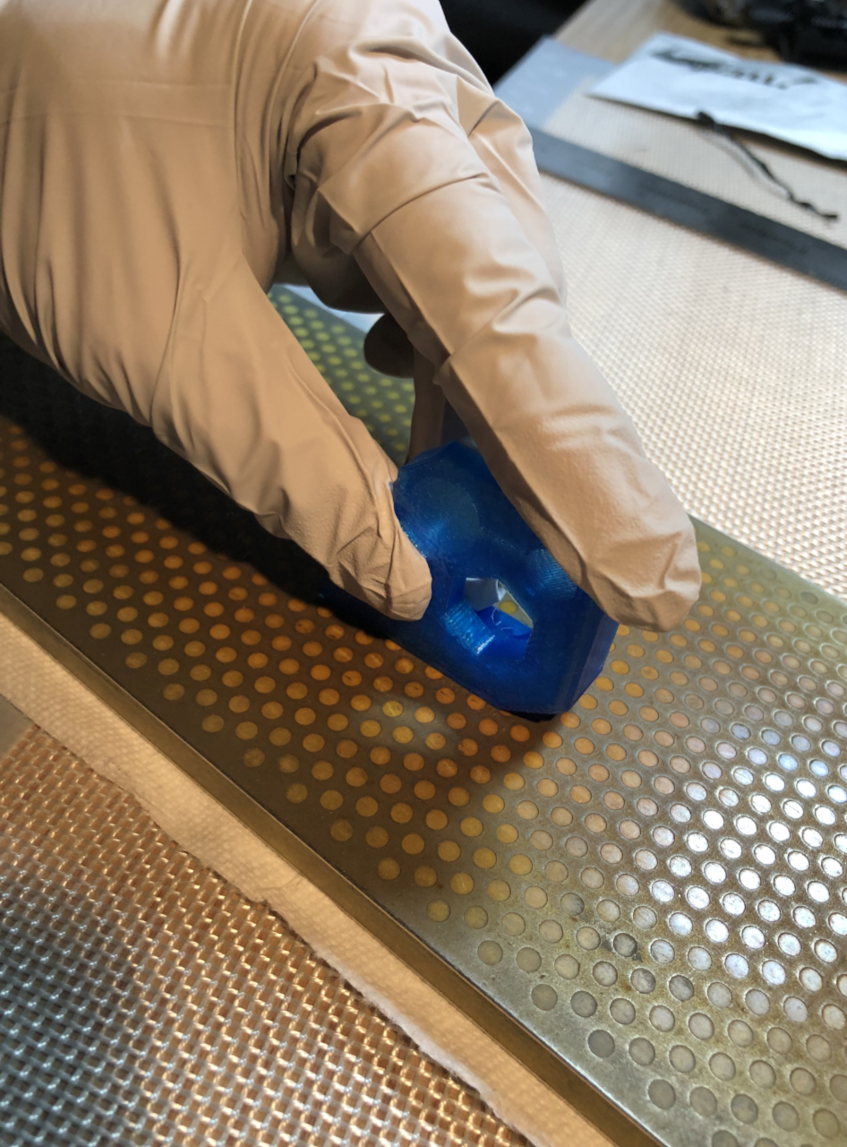
Very lightly lap the ends of the extrusions on a diamond sharpening plate and examine the wear pattern created. If it reveals high points, continue lapping while applying light even pressure to remove those high points. Rotate the extrusion 90 degrees every few strokes to help maintain even lapping. Aim to remove the bares amount of material to achieve high point free ends. You do not need to remove all the power coat and get to bare metal. Just remove high points and burrs (if any).
Plastic Mount Pieces (required)
Plastic rod and motor mounts are 3d printed. As such, their mating surfaces are not perfectly flat, free of elephant footing, nor are they exactly square. Lapping easily makes plastic mating surfaces smooth, flat and square.
Wet sand with 600 grit wet/dry upon a glass plate or diamond plate to flatten mating surfaces . Check with a small machinist square that the surfaces are at right angles. If angular error is found, alter pressure and direction during sanding bring the mating surfaces into square. Aim to remove all high points and get at least 75% of the surface flat. The result is a smooth, continuous flat surface, but does not need to be a polished surface.
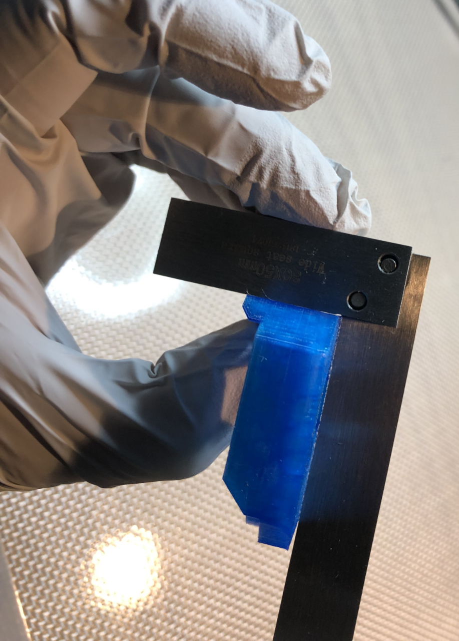
Here the mating surface is slightly out of square. Short arm of square is against mating surface. Long arm of square is slight misaligned from corresponding perpendicular surface. Lapping will correct that issue, but don't take off excessive plastic.
With flat, squared mating surfaces, your parts holds together accurately and stable with less torque.
Z-Axis
The Z-Axis rods are not particularly prone to problems when inexactly parallel. Thus, the technique employed here is crude compared to what we will later do on the Y-axis. We should not need to a huge amount work on the Z-axis, but you can expect get them to within 0.2 mm parallelism. We will further refine YZ plane squareness during later work on the Y-axis.
Large spacing between Z-rods makes caliper measurement of rod spacing impractical. Fortunately, the needed precision is within the accuracy of the Prusa vertical bracket's X-Z plane. That piece has squared tops, sides and lower edge of its upper bridge. You can verify that with your machinist square and caliper. We take advantage of that and visually align (in XZ plane) the rods against the vertical bracket. We can also verify that the rods are equidistant (along Y) from rod to surface of the bracket.
You should have already flatted and squared the mating surfaces of the Z motor mounts and z top rod holders.
Notice that the motor mounts and top rod holders each have some of play in their mounting position. You can shift their positions slightly left/right to adjust Z rods in the XZ plane.
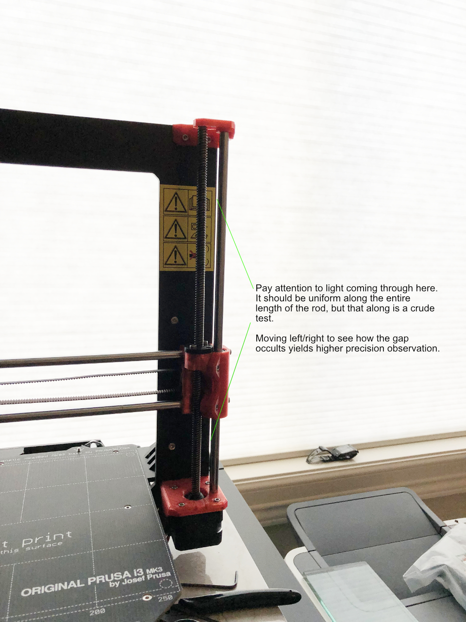
Shine a light to fully illuminate the wall behind your printer. Stand about 1 meter nearly in front of the printer. Observe how the Z-rods and outer vertical edges of the bracket occult light as you move your head left/right. Occultation should be simultaneous along the entire Z-rod if it is aligned correct in the XZ plane. If you see occultation start at top or bottom rather than simultaneously, the rod is tilted left/right. Adjust the Z-rods by shifting motor mount and/or top mount to correct detected left/right tilt.
If tightening the bolts shifts plastic mounts out of desired position, consider adding a washer under the bolt heads. That can reduce shifting induced by a bolt head biting into the frame.
If you see the middle of the light gap occult out of sync with top and bottom, your Z rod are laterally stressed by the x-axis length not matching the distance between z-rods. Check that your x-rods are properly seated into the x-ends. You may need to shift both motor and top Z mounts laterally to match the x-axis length. Alternatively, If you have an adjustable length x-end as in the Bear x-axis, you can adjust the x-rod length bolts.
This makes the Z rods equidistant in XZ, but we must also get them into the same plane.
Caliper the front/back distance from z-rod to the vertical bracket. Check at top and bottom of each Z rod. The distances should be identical at the top. The bottom distances must also match each other. To adjust the distances, you must lap the mating surface of piece(s) having the longer distance. Ideally the gaps become identical at all four ends. That would bring the rods parallel to the vertical plate. If you can't achieve that, aim to get the left top to match right top and the left bottom to match right bottom. That won't be square with Y but parallel with each other.
Recheck light gap occultation and fine tune left/right accordingly.
X-Axis
The X-axis is the most constrained of the three printer axes. Rod to rod spacing and orientation are locked in by the x-axis brackets. What could we possible refine here? --- squareness against the Z-axis.
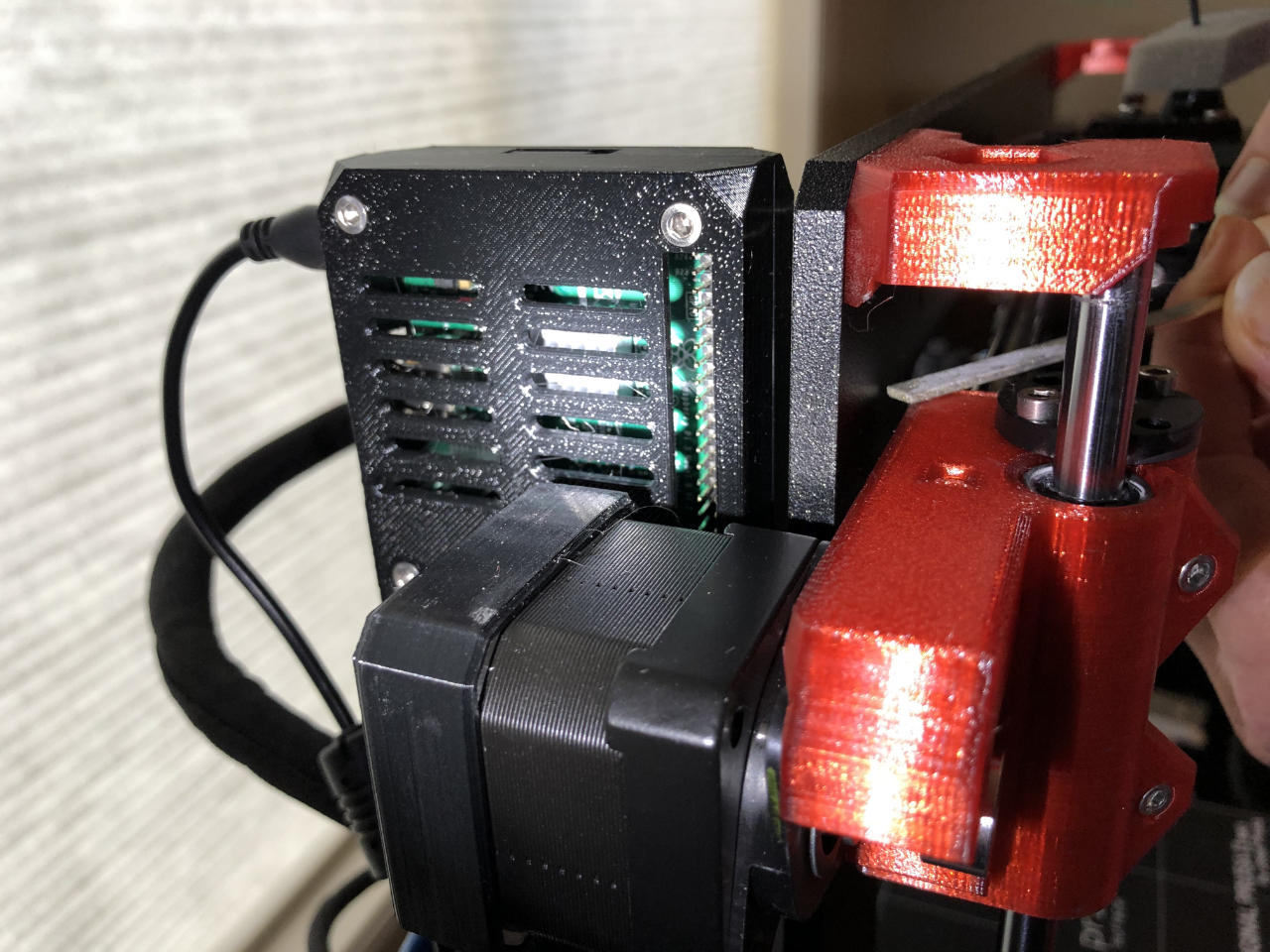
Left and right ends of the X-axis are moved up/down by synchronously driven Z-motors. Those motors synchronize their positions by moving the x-carriage all the way up until the motors meet resistance. Ideally, both sides hit their end "stops" at the same height. It all depends on the particular plastic motor mount and x-idler end pieces you were supplied. The Z end stop occurs when those plastic x-axis pieces hit the mounting bolt heads of the top Z-mount. The bolt heads don't shift much. They are threaded into the vertical bracket. The threaded hols don't move. However, the accuracy and shape of each plastic piece varies. If one plastic is a big taller, it hits the the bolt heads first. That end of the x-axis ends up slightly lower than the other. The x-axis is no longer square with the z-axis.
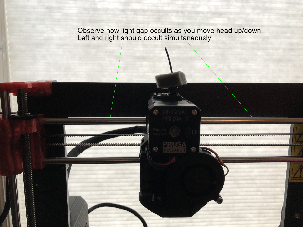
Let's begin by checking how perpendicular the x-axis is with the z-axis. You can't use a machinist square to check x rods against z rods. Fortunately, we already aligned z-rods parallel to the vertical frame. We also know the horizontal bridge edges of the bracket are perpendicular to its left/right edges. We can employ a visual occultation test to check whether x-rods are parallel to the bracket's horizontal bridge bottom edge.
Raise Y to bring an x-rod into proximity of the bracket bridge and look at how the gap occults.
If occultation is simultaneous on left and right, your x-rods are already perpendicular to Z and you are done with the x-axis.
If the gap is uneven or the occultation is non-simultaneous, you must modify the LOWER side's plastic x-end piece to let that side go up higher. For instance, if you find the left side is lower, you will file down the left x-end's impact point.
The process is conceptually simple.
Move Z up until you hear the z-motors miss steps (brrt brrt brrt).
Z motion range may stop you before hitting physical top. You want to go all the way to physical stop.
Permit the printer to go travel further up Z by hitting the reset button while x-carriage is raised.
That zeros the coordinates and the printer won't know to stop itself.
If you get stuck with Z unable to move far enough down, do an "auto home"
In other words....
Move Z up to physical stop (BRT BRT BRT)

Move Z back down to occultation observation position

Check x-axis occultation against bracket horizontal bridge
While x is not parallel with bridge
File off a TINY TINY amount of plastic from head contact points of x-end on LOWER observed side.
Move Z up to physical stop (BRT BRT BRT)
Move Z back down to occultation observation position
Check x-axis occultation against bracket horizontal bridge
Wend
BTW you will see your thick, aluminum, vertical bracket flex an amazing amount when x-ends hit the bolt heads.
Be sure to clear away filings when done.
Congratulations, your x-rods are perpendicular to z-rods.
Now is a good time to take a break. The next steps getting y-rods parallel and perpendicular to both X & Z, lapping Y-carriage bushing seats, and evening out the print surface will take more time than everything prior.
Y-Carriage Part 1 (Optional)
Whether by machining or power coat irregularity, the y-carriage does not always perfect align linear bearings. However, the Prusa printer design tolerates some misalignment. Fine tuning the Y-carriage is an optional refinement. This is sensible only if you already have tight tolerance bearings, rods and want them performing at their best. Otherwise, the stock configuration is "good enough" for most people.
The Y-carriage has three, pre-cut openings into which LM8 linear bearings are bedded. Bedding flaws shift linear bearings slightly out of coaxial and parallel alignment. Angular and radial deviations consume available bearing error tolerance. We can achieve near perfect coaxial alignment and parallelism by lapping the beds like rifle scope mounts.
----------
Tools and Materials Needed
Digital Caliper - Must be accurate to 0.01 mm
iGaging ABSOLUTE ORIGIN 0-8" Digital Electronic Caliper works well and is reasonable $54 cost
https://www.amazon.com/gp/product/B00K3PZVKG
Wet or Dry 800 grit sandpaper. Thinner is better. Sanding film is best if available.
3/8 inch thick float glass plate 5" x 8"
----------
Method
Remove Y-carriage from printer and dismount linear bearings and Y-belt holder. Now is also a good time to IPA clean and re-lubricate your bearings.
Use a Sharpie and mark each bearing to indicate positions of ball rows. The marks later let you locate ball rows without reinspecting bearing interiors.
Check both surfaces of Y-carriage against a flat surface for warpage. If any warpage is detected, correct that before going further. Granite counter tops are fairly flat, if you stay away from the edges. Mine measures flat +/- 1 mil over 6 inches in the center. Areas near edges are easily 10 or more mils off. Ideally we would check against a surface plate, but that's not available in most homes.
Place Y-carriage on a level, flat surface.
—- Two bearing side
Place LM8 bearings in the DUAL bearing side of carriage. Ball rolls should be at 12 and 6 o'clock positions (top and bottom).
Feed a 8 mm linear rod into both left side bearings. Don't angulate or force the rods. Leave the exactly the same length of rod extending out each end of the bearings. The rod should be balanced on the two bearings.
Check rod positions to determine what needs to be done during lapping. Deviation in the xy plane is typically very small. Mine measures only 0.14 mm deviation between the front and back of the print bed.
The main deviation to correct is in y-axis.
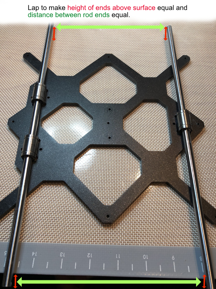
Use your caliper to measure, on each end, how far off the surface the rod end sits. Both end heights above surface should be equal. If one end is higher, make mental note of which end. The bed for that bearing will need to lapped more to lower that end.
The goal isn't to remove a lot of material. We want to remove just the barest amount. Take off too much material and the bearing will seat to deeper.
We lap the beds using the bearings and rod to guide our motions. You must take great care to avoid getting any grit into the bearings. Rifle scope mount lapping uses lapping paste but that is too risky around our bearings. Instead we will use thin, fine DRY sandpaper. With careful technique, your sandings will remain outside of the bearings.
Vacuuming the work pieces between each lapping step is highly recommended.
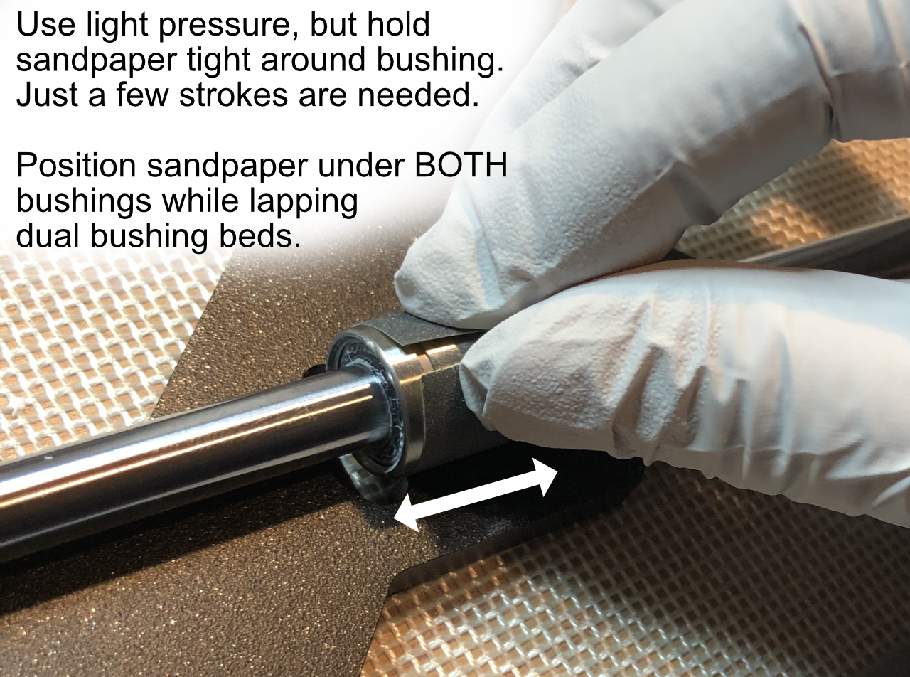
Cut two pieces of 800 grit paper sized to wrap around a bearing. We prepare TWO pieces because we want both bearings supported by the same thickness of sandpaper. That keeps the rod parallel with the carriage plane. If we placed sand paper under just one bearing at a time, the thickness difference would throw off alignment. The thinner the sandpaper you can find the better.
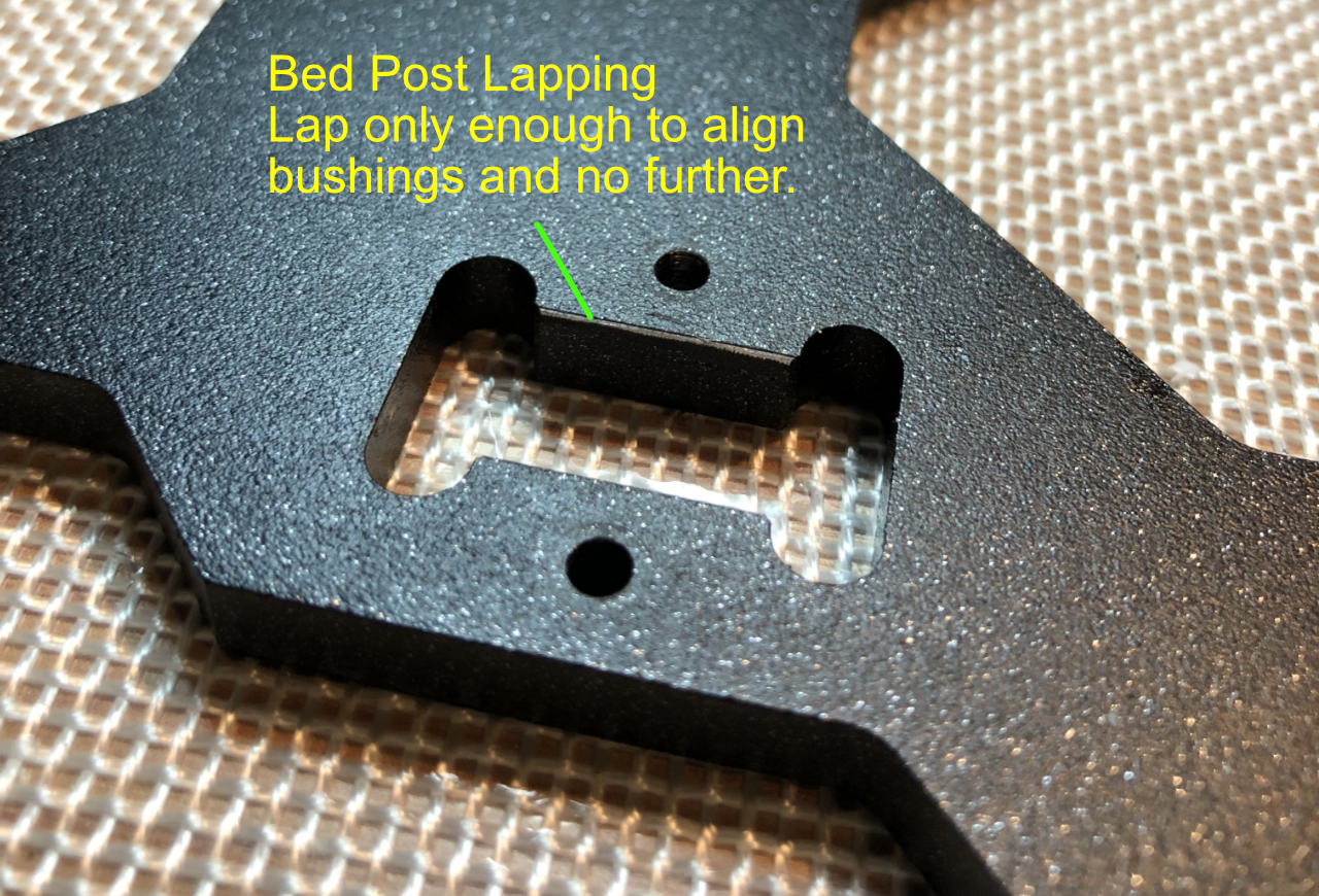
Technique is to move a bearing back and forth on its rod with sandpaper wrapped around its body. The bearing acts as tool piece while the rod maintains alignment. Apply light pressure on the rod (between the bearings) to stabilize position during lapping. If you need to deviate the rod to effect a change, apply slightly more pressure in the direction you need. You can only move a small distance with each stroke. NEVER rotate the bearings around the rod. Only move back and forth. Lap each bed enough to remove the power coat and expose a tiny bit of metal. That's probably about 10 to 20 light strokes.
If one end of the rod was measured higher, the corresponding bed needs more strokes or pressure to lower that end.
If you have a known y-rod and print bed y-axis misalignment, you can also slightly correct the deviation during lapping, but I would hesitate to do much lateral deviation. You will remove too much metal.
Clean up all lapping dust. Recheck how the bearings and rod lies. Repeat until both ends of the rod are same distance above surface. The beds now naturally hold the dual bearings coaxial and parallel to plane of y-carriage.
A lapped bed looks like this once complete. Don't remove more material than in this image
Y-Carriage part 2 (Optional)
— Single bearing side
Our goal for the single busing side is to make the bearing naturally bed parallel with the dual bearing side's rod.
Place an LM8 bearing in single bearing bed. Again, ball rows should be at 12 and 6 o'clock (top / bottom).
Feed 8 mm linear rod into single bearing. Position rod exactly centered in middle of bearing so it is balanced.
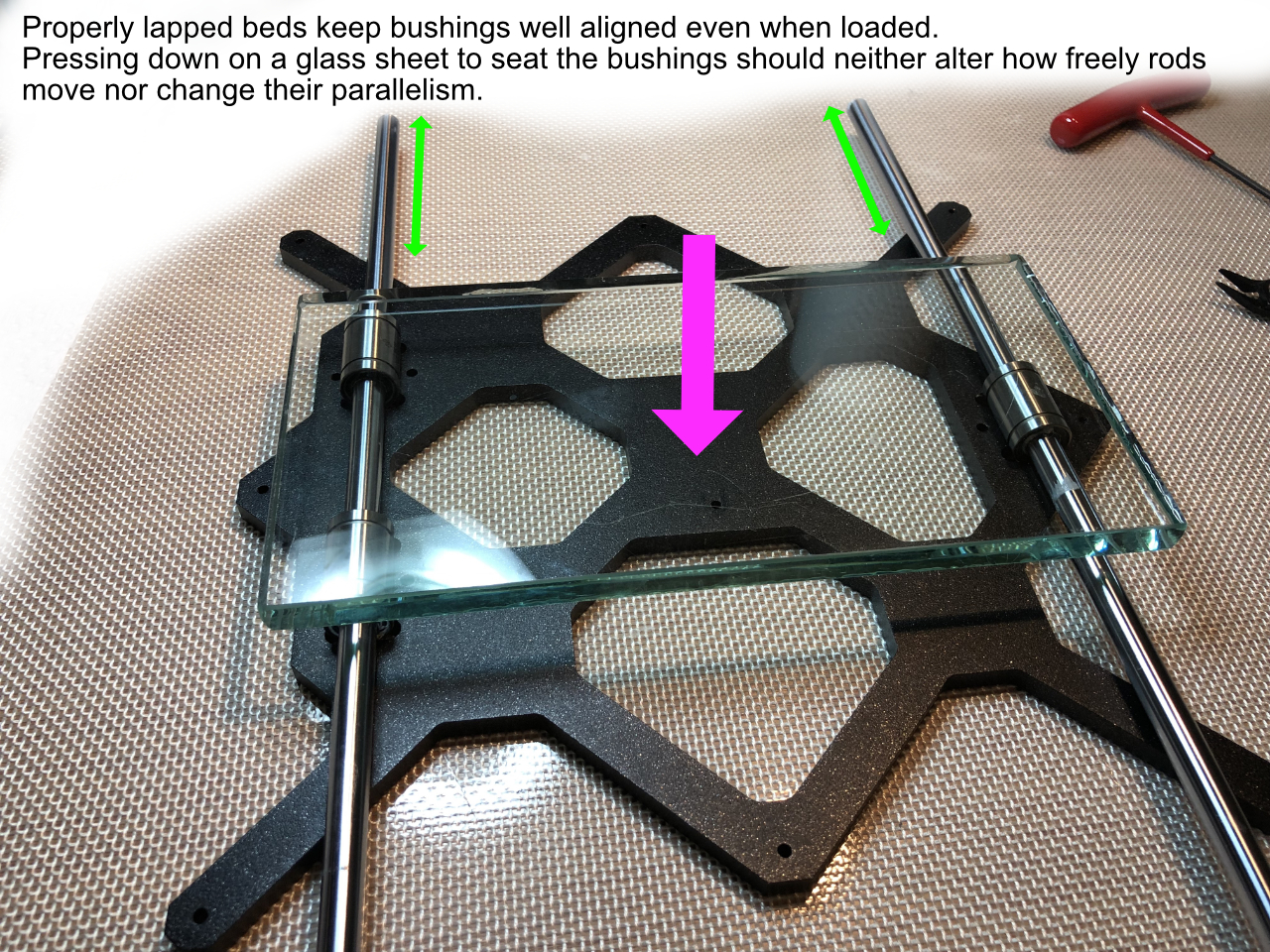
Both Y-rods should be freely balanced and resting on their respective bearings. Placing a flat glass plate across all three bearings can fully press them all into their beds.
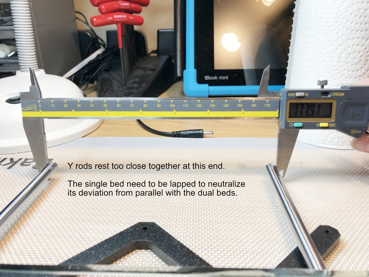
Measure the distance each rod end is above the surface. Also caliper the distances between rod ends. Visualize in your mind, what direction you must deviate the single bearing rod to render it parallel with the other daul bearing rod.
While lapping the single bearing bed, hold one end of the rod in the position that aligns the rods parallel. Frequently recheck spacing and end heights. When completed, both rods should rest parallel with each other and the y-carriage plane.
Verify the rods move freely when all three bearings are pressed down with a glass plate. If the dual beds are lapped coaxial, pressing down on the plate will not bind the dual side rod.
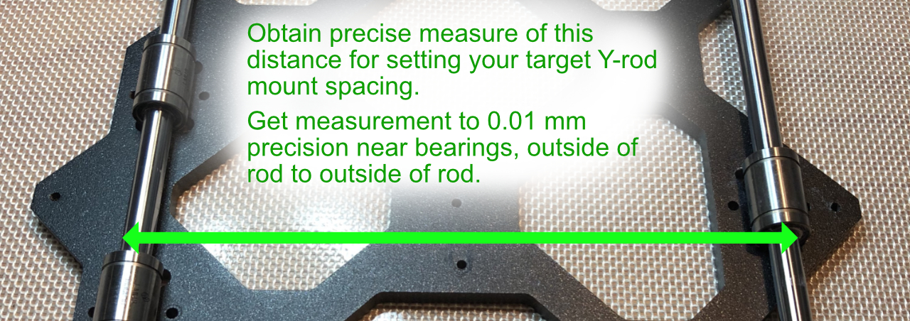
Now that your bearing beds hold bearings and rods parallel, measure the spacing between the rods near either end of the single bearing. From outside of rod to outside of rod, this is about 178.00 mm. Write down the actual spacing you measure. You want that distance down to the 0.01 mm accuracy. That is the neutral spacing of your y-rods. You will refer to this distance later while adjusting y-rods spacing.
For the remainder of these articles, I will use 178.00 as Y rod reference distance.
-
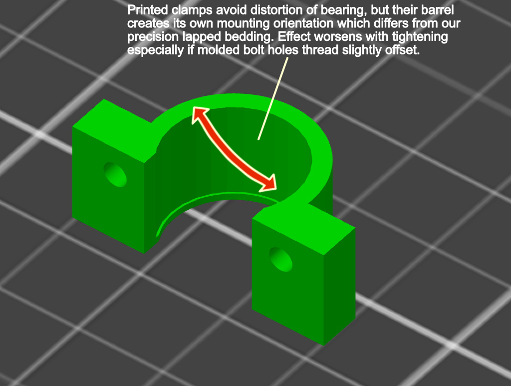
Getting the beds perfectly lapped to support the rods parallel isn't enough to ensure the bearings and rods are well positioned. Tightening the u-bolts can deviate or deform the bearings. Even if you print new plastic clamps, those will also deviate the bearings. Printed plastic clamps create their own positioninging determined by their bolt hole positions. Tighten them down and they will override your perfectly lapped beds.
My solution is to lightly tighten the u-bolts, just enough to avoid motion. Once final assembly and adjustments are are completed, I cement the bearings with a small bead of epoxy at each bed edge. That firm affixes the bearings without disturbing their bedding.
For now, attach the bearings with u-bolts just tight enough to not let the bearings fall off your carriage.
Re: Planar, Parallel and Square
As preview, here is how freely the y-carriage will move once we reinstall the rods perpendicular to X&Z, parallel to each other, and spaced to match your carriage's bearing beds.
The y-belt is detached to illustrate just the bearin and rod resistance. Resistance is so low that just heatbed cable tension moves the carriage.
This was recorded with Misumi rods and bearings installed and post my full xyz tuning procedure.
[youtube] [/youtube]
Y-rods are next....(assuming there is any interest)
Re: Planar, Parallel and Square
Yes there is interest.
Thank you for your hard work and sharing this information.
KR
Andy
Normal people believe that if it is not broke, do not fix it. Engineers believe that if it is not broke, it does not have enough features yet.
Y-Carriage P3
A few more points to clarify regarding Y-carriage before we move on.
This is where to measure your y-rod spacing. We take it near the bearings because its physically most stable there. You could also measure from inside of rod to inside of rod, but I found it much easier to caliper outside to outside at this stage and also during rod mounting.
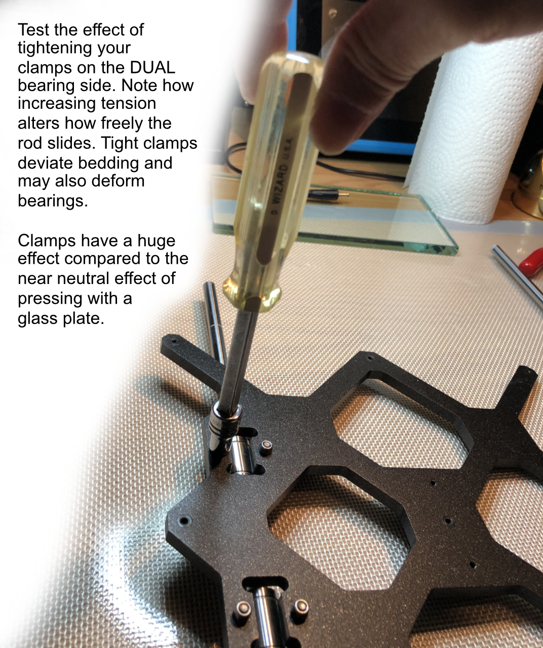
Plastic straps are available on Thingiverse and while they do indeed avoid deforming the bearings with too much tension, they aren't a panacea. You can't crank them down all the way without creating deviations. They have their own barrel shape and that gets forced into a different orientation as the clamp is bolted down. We just lapped the beds to allow perfect alignment. Tightening a printed, plastic clamp pulls things out of alignment. For the "good enough" crowd, that's fine, but you will notice even plastic clamps create more binding when tight.
Flipping over the y-carriage and test on the dual bearing side if you want your own proof. Test on the DUAL side because you'll detect alignment changes readily on that side. Also, the single bearing side is prone to accidental axial overloading if you angularly deviate the rod.
BTW, hold your rods while flipping the carriage and always flip it side to side, not end over end. Rods will fall out and may damage your bearings on
their way out.
When we finally get to mounting the y-rods, our goal is to get the rods perpendicular to the x and z rods. It is the relationship between rods that determine how the machine moves. The usual proxy of aligning against the frame gets you close, but we're after getting the rods planar, parallel and perpendicular.
I should have mentioned this next tip earlier...
TIP: When mounting your Y-carriage bearings, test all each row at the top rail position. One row may slide more easily. Orient the bearing so that best row is the one the rod is riding upon.
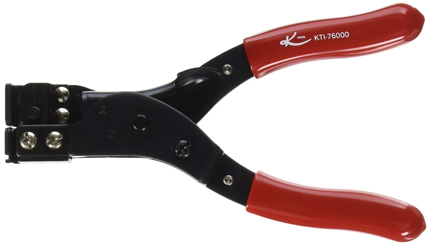
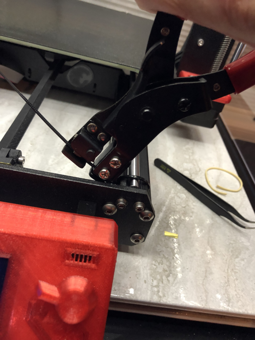
Nylon Tie Tightening Tool
This nylon tie tightening tool is one of those things you never thought you would want or need -- until you use it for the first time. Then you wish you got one years ago. I simply won't hand tighten zip ties any more.
The tool tightens ties more securely and controllably than possible with fingers and pliers. Don't tighten so hard that you break ties, but you'll easily get all your printer ties to desired tautness. For securing the y-rods, this tool creates secure, consistent results. Highly recommended.
https://www.amazon.com/gp/product/B002XMQOE4
$14 and worth every penny!
Planarity Testing with Glass Plate
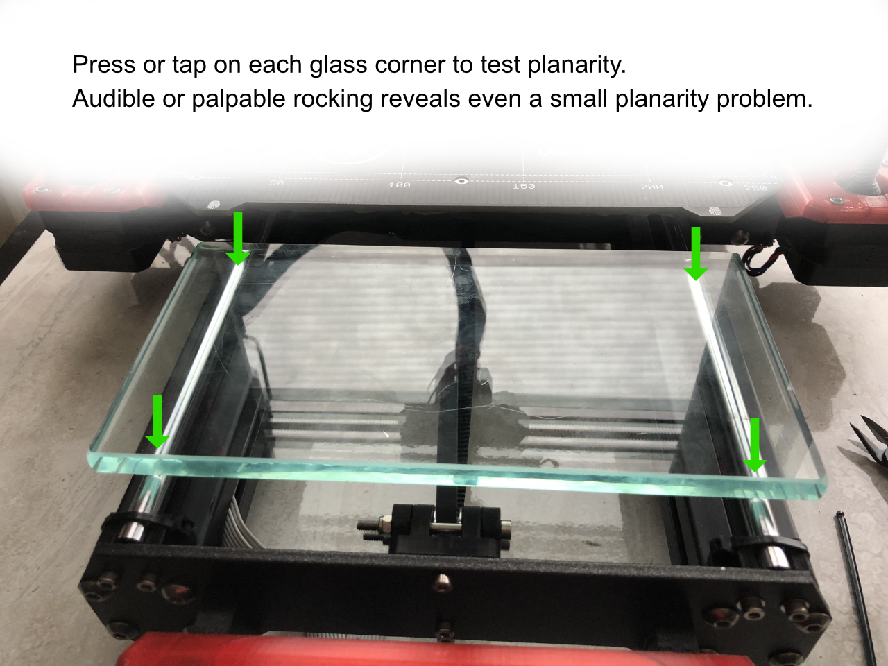
Here is an easy and sensitive method for checking if pairs of rods are in plane within 20 um at their ends. Feel what happens when a flat glass is placed across a pair of rods. If the rods are in plane with each other, the glass sheet will not rock. As little as 20 um of difference in rod end planarity is readily detected.
Use a 5 x 6 or smaller piece of glass for testing planarity. A larger piece is too heavy and distorts rod geometry. That obscures planarity issues that would be readily detected. A smaller, lighter piece enables yields more sensitive results.
For example, after we remount the y-rods, you can lay a glass plate across the y-rods. Never drop your plate onto the rods with any force or at an angle. The glass is harder than the rods and can scratch the rods with careless technique.
Lightly tap on each corner of the glass. Feel and listen for any rocking. You can detect non-planarity and which direction rods must be adjusted with this technique. I recommend also testing with the plate in flipped/rotated orientations to verify there isn't a problem with your glass plate being curved.
I will assume you have a flat piece of glass for the remainder of this thread.
When rods are in plane, your glass plate will be supported with absolutely no inducible rocking.
This technique can detect when an end of y-rod is as little as 20 um too high or low.
We will later shim y-rod heights to make them completely planar. There are a some steps before that, but we'll be aiming to get the rods truly planar, parallel and perpendicular.
——
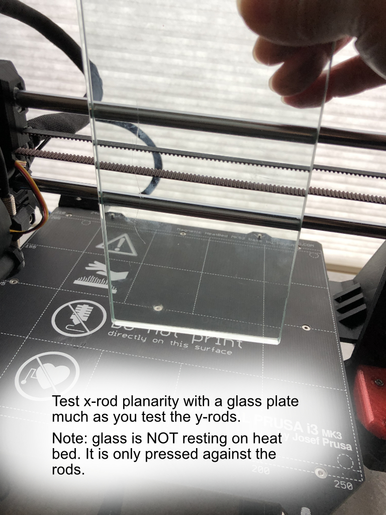
x-rod planarity can also be checked by pressing your glass plate against the rods and checking for any rocking. In the case of x-carriage, non-planarity can be corrected by twisting the x-ends into alignment.
Y-Rods part 1
Y-rod alignment is the most difficult step because we must make the rods perpendicular to both x and Z rods while still getting both y-rods parallel and accurately spaced apart. Notice, we are aligning rods against rods, not the frame. Getting the rods into correct relationship is paramount. The frame can be off kilter, but we must get the rods parallel and square. The rods define motion axes, not the frame.
The process may take several rounds to get everything simultaneously correct.
We will iteratively...
Shift left y-rod perpendicular to x-rods.
Shim left y-rod perpendicular to z-rods.
Shift left/right y-rod distance equal to that we measured while preparing the y-carriage.
Shim right y-rod planar with left rod.
Shim left or right y-rod making print bed level with x-rods
Secure y-rods with zip ties
Recheck and repeat until satisfied with all measures.
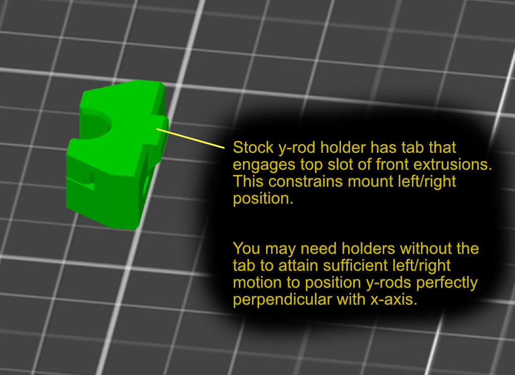
Examine how the y-rod mounts work. They are bolted to the rear and front printer brackets, but the mounting holes allow a small amount of play. We take advantage of that play to get the rods into good alignment. Each stock mounting bracket has a bottom tab. The front two holders engage their tabs with the extrusion top slot. That tab can limit left/right movement. You may need to cut off the tab or print a version without the tab to get enough left/right motion in the front mounts. Also, the mounting holes themselves may limit you. It is permissible to widen the FRONT mounting holes with a file. However, do not enlarge the rear mounting holes. The front mounting holes have the advantage of the extrusion setting a bottom limit for position. You don't have that in the rear. Enlarging the rear mounting holes risks lowering the mount excessively.
We will make lateral adjustments using the wiggle room of the mounting holes. We will NOT make vertical adjustments via the mounting holes. Always press the mount all the way DOWN when they are being bolted in. If you try to raise a rod end by bolting a holder higher, it will slip down the first time the bed encounters a larger load.
Here is a link to my tab-less version of the y-rod holder. You can alternatively slice off the tabs of your existing holders.
http://www.cosalient.com/public_html/picture/PRUSA/y-rod-holder%20No%20Tab_0.15mm_PET_MK3_0.15mm_PET_MK3.stl
You may notice that tightening the mounting bolts shifts the mounts from the position you want. Add 3 mm washers under the heads to reduce this tendency.
----
Attach all y-rod holders loosely to the printer frame.
Linear bearings should be secure, but allow free rod motion. Attach heat bed using stock standoffs or otherwise neutralized adjustable standoffs.
Mount your rods and y-carriage onto the mounts. Take care to snap both rear ends down simultaneously and front ends down simultaneously. Simultaneous snapping avoids axially over-stressing your bearings. If you need to lift a rod end, also lift is companion rod.
Do not connect the y-belt yet.
Do not zip tie your rods yet. We'll do that later.
Concentrate on aligning the left rod (dual bearing) first.
The left rod will be the master Y-rod. Its orientation will determine the right rod's final position. Technically, this aligns the heat bed's X&Y against the x-rods, but my measurements of heat bed vs y-rod axis deviation show this is an adequate (within 0.15 mm) and easier proxy
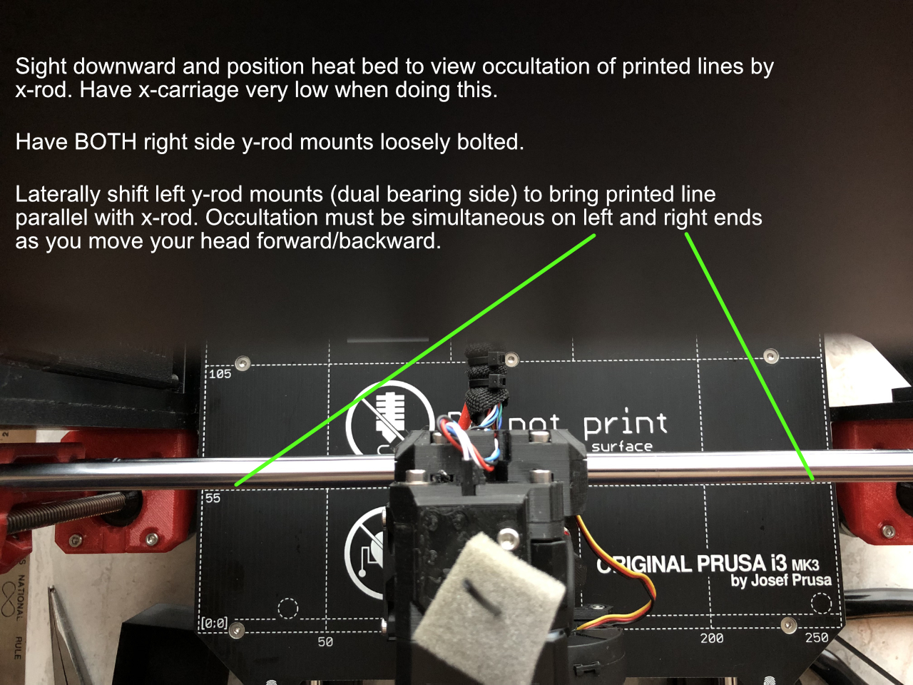
Use the visual occultation method to get the left y-rod perpendicular to the x-rods. Shift left side mounts left/right to get xy skew minimized.
If you achieve simultaneous occultation, the skew will be quite low - about 0.2 - 0.3 mm skew. We can further refine this with a microscope, but this will already get skew low enough to register as perpendicular during XYZ calibration.
Tighten both front and rear left y-rod mounts and recheck alignment. Repeat adjustment of the left side until you get xy perpendicular.
Next, we must adjust the left y-rod perpendicular to Z rods.
Y-Rods part 2
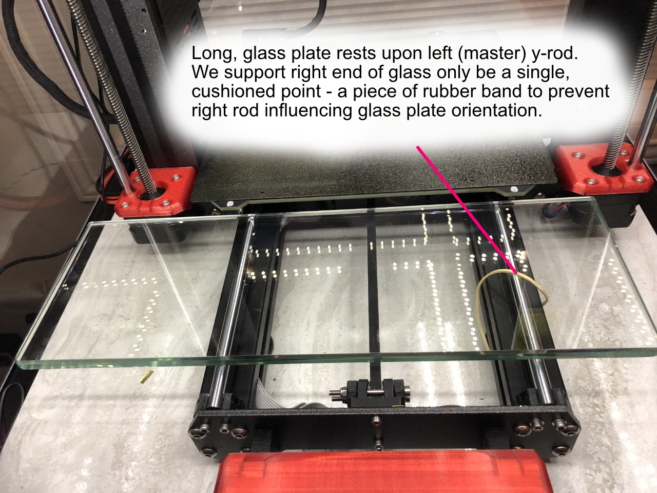
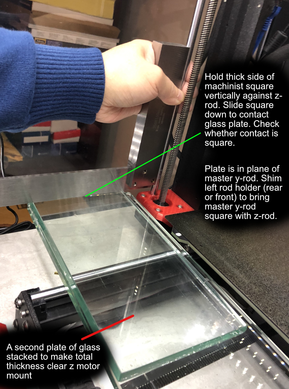
We use our long glass plate to extend the left y-rod's plane out laterally to test against the left z-rod. I refer to the left (dual bearing) y-rod as the master y-rod because that is the one we set perpendicular to both x and z. The right (follower) y-rod is later adjusted to be planar and parallel with the master y-rod. Depending on the thickness of your long glass plate, you may need to stack a second plate upon it to clear the z-motor mount.
We don't want the follower y-rod to influence testing of the master y-rod. So, we isolate our long glass plate from the follower's orientation by making the right side support only a single point. A piece of rubber band is a nice, cushioned single point support.
Now we can check the master y-rod squareness against left z-rod by verifying squareness between the glass plate and z-rod. Use an architectural square or (better) machinist square to check squareness between z and y. Best technique is to gently hold the thick side of your machinist square against the z-rod and gently slide downward until the square contact the glass plate. Check how square the glass is contacted. That lets you know if the master y-rod needs to be adjusted.
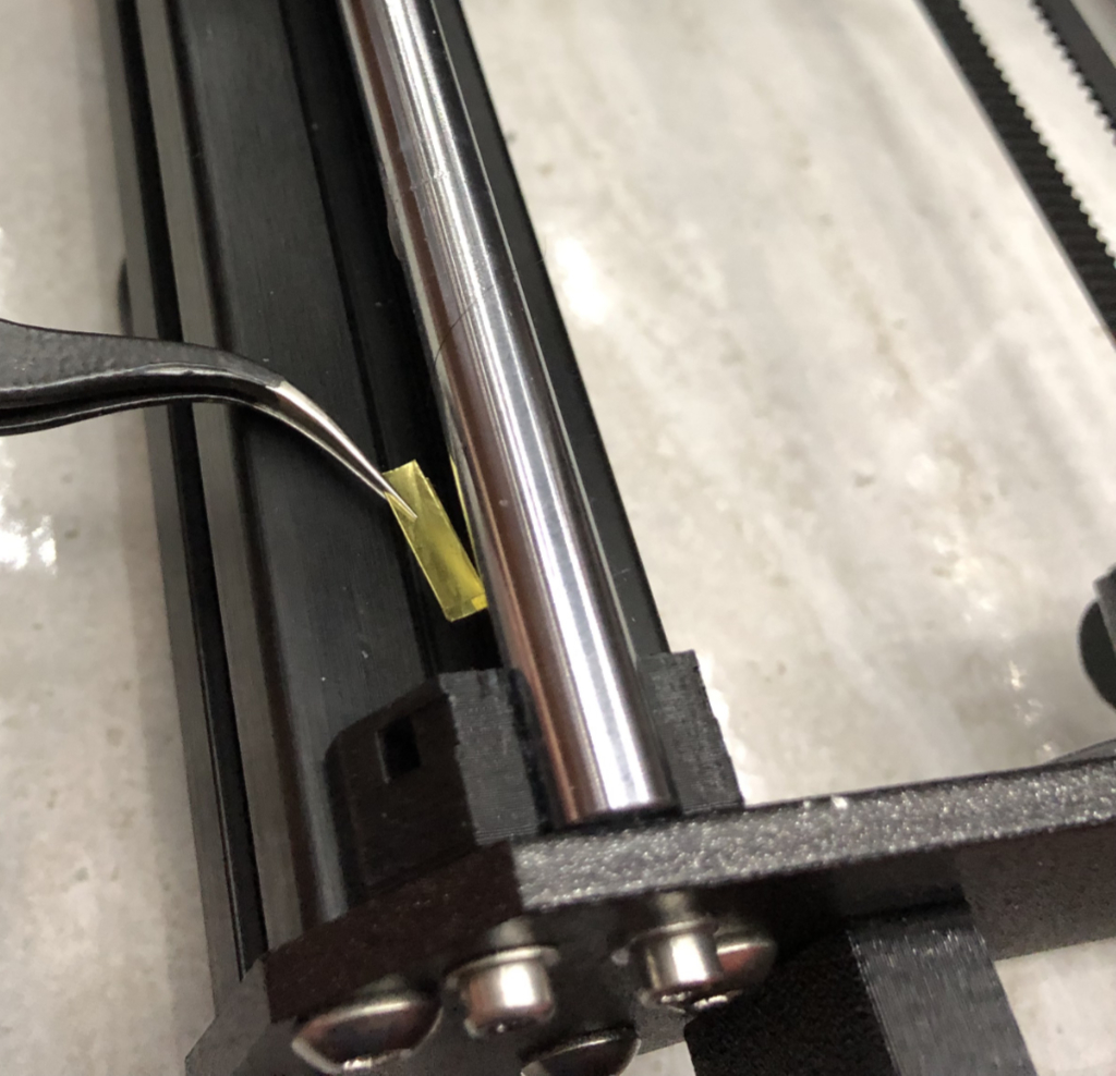
If not square, shim under the low end of the master y-rod with brass shims.
Be sure to REMOVE the glass plate(s) before lifting the rod end for shimming.
Raise only the barest amount needed to feed shims under the rod.
Your shim pieces should be about 10 mm x 4 mm in size. Curl them to match rod shape before insertion. You will need to experiment to get the right combination of shim thicknesses
Good tweezers are a must during shimming.
Shim, re-test, repeat until square.
Your master y-rod is now square with both x and z rods.
Note: If you are having trouble obtaining a long glass plate at a reasonable price, a piece of glass shelving is sufficiently flat. I tested one from Amazon for $17 and although not perfect, its flatness meets our needs. It is however, far too heavy to use for planarity testing. Only use for getting master y-rod square with z-rod. https://www.amazon.com/gp/product/B0111KLQHI
Y-Rods part 3
We now work on making the right "follower" y-rod planar and parallel to the master y-rod.
Equidistant
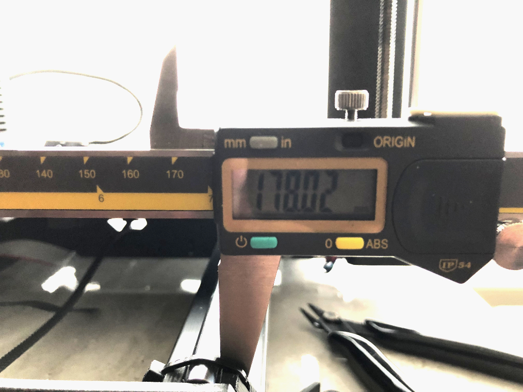
First we make the spacing between the rods equal to the distance you measured during y-carriage preparation. That should be near 178.00 mm. Use the value you measured, but for simplicity I will write 178.00 mm in this thread.
Set your digital calipers to 178.00 mm and lock the jaws in place. Use the calipers to roughly guide each rod end's distance as close as possible to 178.00 mm. Partially tighten right rod mounting bolts. Nudge and measure until you get bolts tight and the distances correct. Moving the y-carriage close to the end you are adjusting often helps.
With care you should be able to match front and back distances to within 0.02 mm of each other and planarity within 0.03 mm.
Here one end is almost right!
Planar
Use your small glass plate to check x-rod planarity. Shim the "follower" y-rod to make it planar with the master y-rod.
Recheck rods are still equidistant. Repeat adjustments until you have both planarity and equidistance.
Your y-rods are now parallel with each other and perpendicular to both x and z axes.
NO - you are not done yet. Y-rods may still be one lower than the other. That would still be perpendicular to x & z, but your heat bed will be tilted with one side higher than the other. You could leave this to mesh bed leveling, but it is best to get physical leveling correct and minimize compensation needed for mesh bed leveling.
If you've following the process this far, it has been a lot of work. You are about about 3/4 of the way there!
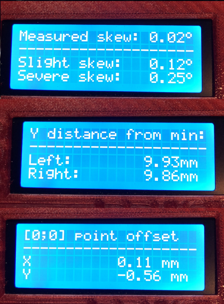
Once you're done, this is the kind of xyz skew results you should achieve...
Beyond that, your xyz print geometry will be as perfect as practical. Also, super parallel rods let your bearings will roll more smoothly. No electronic correction can help your bearings roll smoothly on non-parallel rails.
We next adjust the PLANE of the y-rods to make the print bed level with z-rods. That is the next step.
Y-Rods Part 4 - Heat Bed Left / Right Leveling
Think about the relationship between x y and z axes that would exist if you lowered the master y-rod 1 cm. The rods would still be perpendicular in all axes. They would even be parallel between their pairs, but something would be terribly awry. Your heat bed would tilt badly left. In this step, we level the heat bed by adjusting the y-rod plane.
Go ahead and attach the Y-axis belt. You may need it attached for this step.
Lets ensure the x-carriage is in its "level" condition. Move x-carriage all the way up to actually hit z stops. If it won't go that far, press the reset button to zero coordinate and then make it go up to physically hit z-stops.
Follow that with auto home.
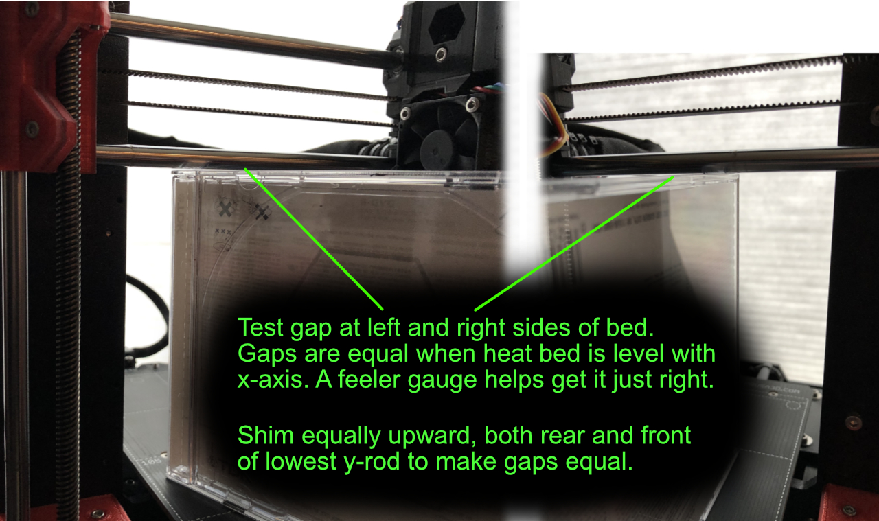
No w that the x-carriage is "level" condition, we level the heat bed surface with the x-rods. We cannot put the x-rod against the heat bed. So, use a CD jewel box to help with the measurement.
Raise Z high enough to stand a jewel box under the x-rods. Slow lower Z until there is barely a gap between jewel box and x-rod. Check on both left and right sides of the heat bed. Do NOT go so low that jewel box and x-rod are in direct contact.
Find the side with the largest gap and shim the y-rod on that side higher. Add the same amount shim for both front and rear y-rod mount. Keep rechecking the gap and shim until the gap is the same for both sides of the heat bed.
The head bed is now left/right level with x-axis.
Fasten the y-rods with nylon ties. A tie tool handily creates tighter and more consistent tension on the straps. I highly recommend using one instead of fingers and pliers.
Now that everything is tightened down, go back and recheck all the y-rods again. Go all the way back to checking master y-rod for z-rod squareness. Adjust and reship as necessary to get it all correct WITH ties secured. You may need to cut ties back off to re-shim.
Congratulations are in order. You have gone through my basic XYZ rod alignment process.
Run XYZ calibration. Set Live-Z
PS. One last option is hyper fine xy skew reduction with a microscope. I will cover that as a final section, but feel free to stop at this point.
XY Skew Extreme - Microscope Method
Hyper-fine xy skew correction goes beyond what you can do with the x-rod/print bed line visual occultation method.
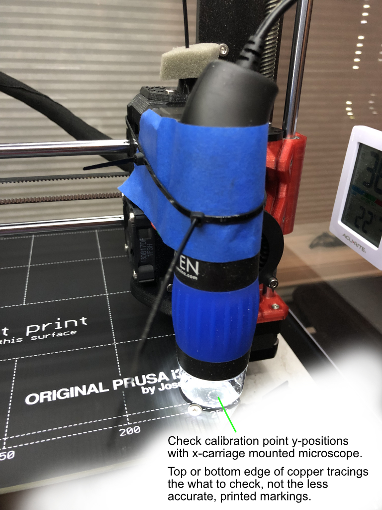
The hardest part is securely attaching a microscope to the x-carriage. I was able to do so with some zip ties. You may need to experiment, but don't damage the carriage or its fans. Also be mindful of the filament sensor cable and connector when attaching your microscope.
Once your scope is mounted, the process is merely to observe the two front calibration pads. Look at the copper tracings, not the printed circles. Run the x-carriage left/right to move between the calibration points while keeping y position unchanged.
Look for difference i the y-position of the copper dot. Either the topmost or bottommost edge will work.
Have right "follower" y-rod mounts loose and adjust master y-rod to get the smallest amount of y-change when switching from one calibration circle to another. Mark the y-position with your mouse pointer for easy comparison as you move from one point to another.
Tighten master y-rod holder.
Re-adjust follower y-rod to be equidistant and planar and tighten up its holders.
Your XY skew is now accurate beyond the deviations the PINDA can detect.
Repeat XYZ calibration.
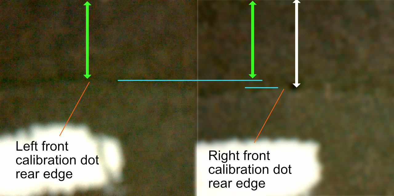
Here are my left and right calibration point micrographs. Notice how small the vertical distance the two points are shifted relative to top of frame. For scale, the white markings are the printed markings on the heat bed.
I think that covers it, folks..
Final Y-Bearing Fixation
I forgot to mention how the y-carriage bearings were attached into their beddings. Up until now, the bearings were only lightly secured. My securing method makes the bearings immobile in their beds. It is absolutely imperative that the y-rods area already fixed parallel.
Once y-carriage and rods have been aligned, remove heatbed and detach y-belt. That leaves the carriage completely free so you can feel any resistance. You already have y-rods adjusted parallel and square, the goal now is to firmly attach the bearings without creating any angular deviation or deformation.
1. Verify bearings are centered front/back inside their bedding openings. If you have the dual bearings too far forward or backward, you can adversely affect y-axis length. The stock configuration depends on the bearings striking the left rod mounts to detect end of travel. If your bearings are shifted forward/backward in their beds, the y travel distance gets changed and possibly cause xyz calibration failure.
Also, physically crashing the bearing against the mounts can gradually shift them. Some of us use an alternative y-motor mount that includes a protrusion that stops the y-belt holder. This avoids the rear left y-bearing from being shifted during future y-axis calibrations.
https://www.thingiverse.com/thing:2809788
You can alternative position the REAR left y-bearing forward so it is already at the front end of its bed to resist impact shifts.
If you achieve proper fixation, your bearings are bedded firmly enough to survive calibration impacts.
2. Loosen the bearing mounting nuts (or bolts if you are using plastic retainers) of all three bearings.
3. Gradually tighten each nut slightly at a time. You should increase tension evenly and distributed among all three bearings. Move the y-carriage as you tighten the nuts and feel for any binding as you increase tension. Back off tightening if you feel any change from free rolling. You should never increase tension to the point of changing how well the carriage moves.
4. Tension on the nuts is probably lower than you reach by following the "90 degree more after touching" described in the stock instructions. Even with perfectly aligned rods, I find that turning nuts full 90 degrees more interferes with how freely the carriage moves.
Your bearings are now secured with the max u-bolt tension that doesn't induce shape changes. It's probably not enough fixation to prevent bearing shifts - especially when the printer rams the bearings against rod mounts. How did I ensure full fixation despite the lower bolt tension? Epoxy.
5. Apply a THIN (ca 1 mm) bead of JB Weld epoxy along the bearing bed edges. You just want to secure the bearings, not make them impossible to remove. Allow the epoxy to harden before disturbing the printer. This creates firm fixation without inducing any position shifts or deforming the bearings. Don't do anything further until the epoxy hardens.
AFTER the epoxy hardens, reattach y-belt, heat bed and repeat xyz calibration.
