PETG corners of prints bending up at around the 1.3mm of thickness
I'm having trouble getting consistent results on a large PETG print. Sometimes it prints without problems, sometimse a small part of a corner will "lift up" a bit, and today I had a lot of pull-up on both corners. The 1st layrer is always good. I slowed down the speed to 80% and set a thickness of .2mm, which for both PLA and PETG produces a great 1st layer.
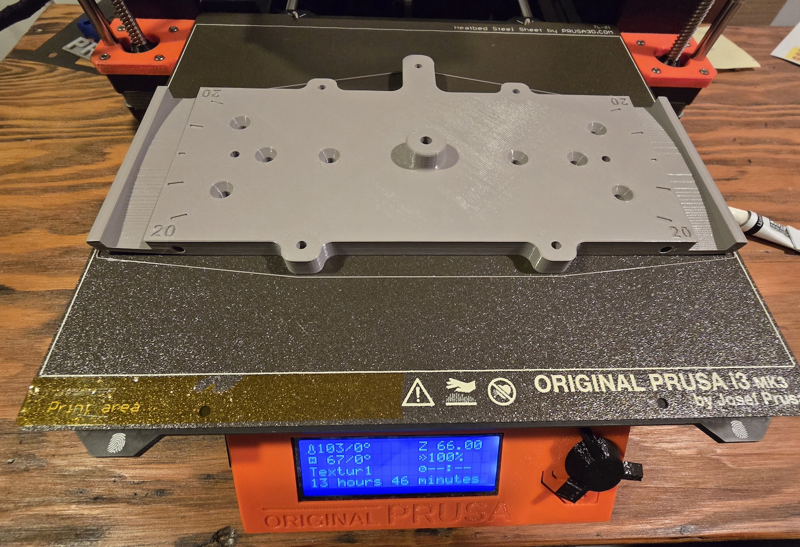
My question is what parameter or design change is needed to discourage this problem? Should the bed tempurature, which is at the default setting, be changed? This is a 14 hour print, and it takes about 2 hours to get to the "lift up" problems to show up.
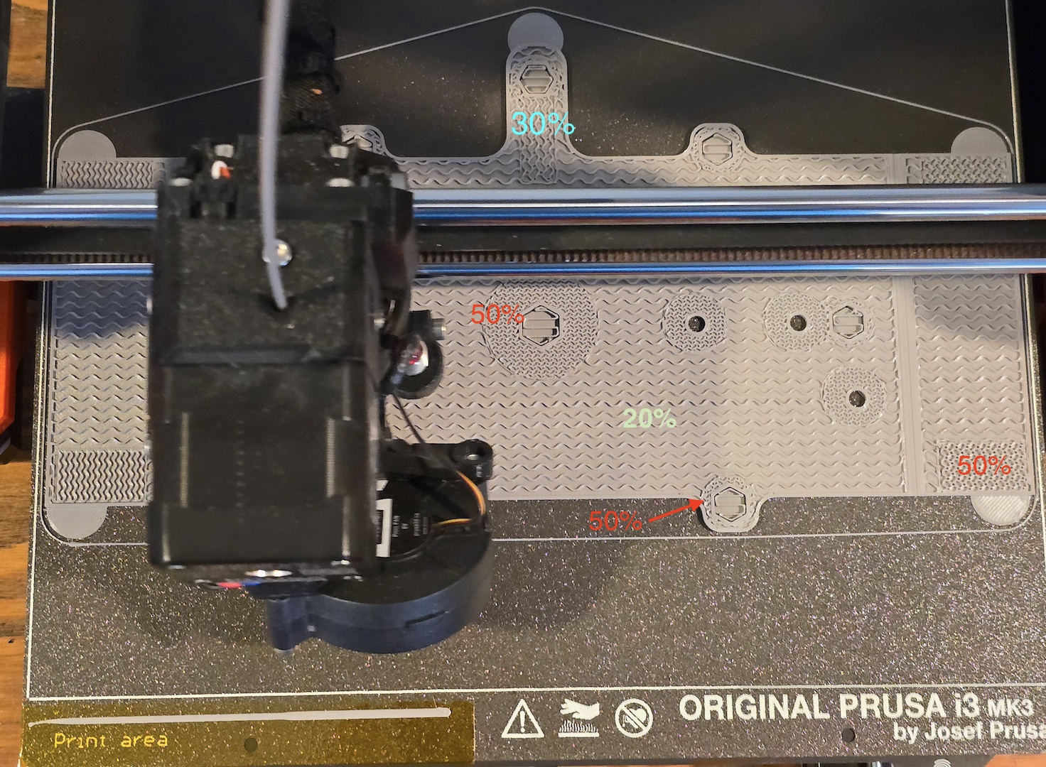
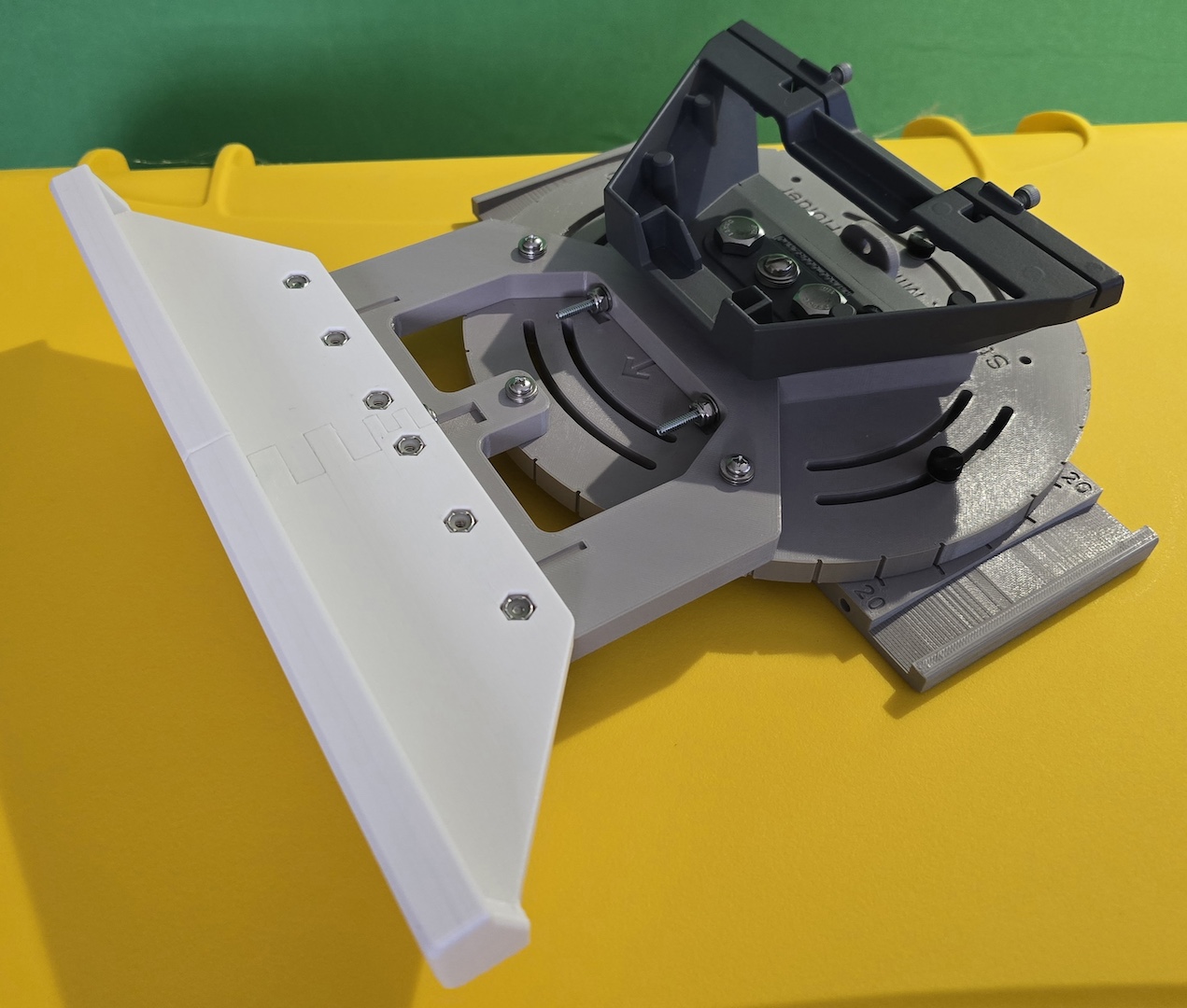
Pictures enclosed. In paritular, note that the percent of fill changes depending on if that section of the part will have metal screws or nuts going throught it. Open areas are 20%, the parts that have metal fasteners on them is 50%. IDK if that makes a difference or not.
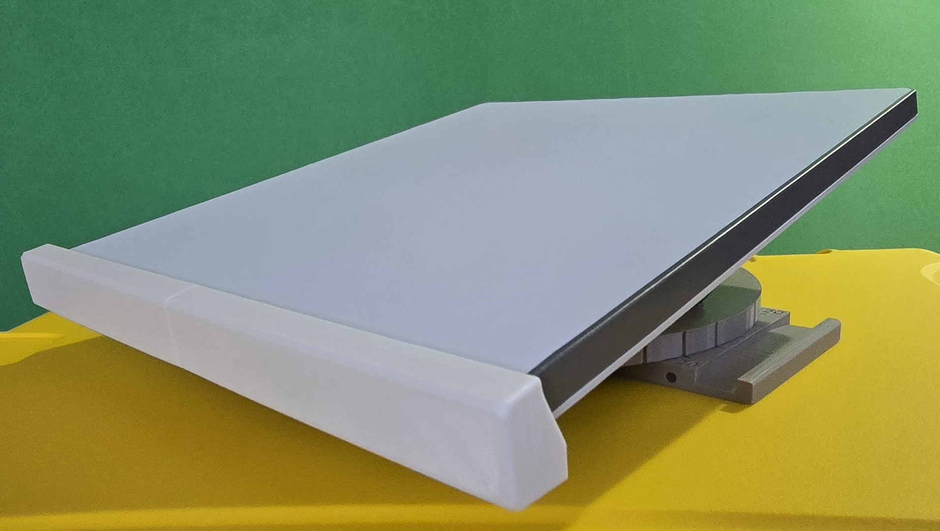
Gratuitous pix of the project, a StarLink Mini holder, included. TIA
RE: PETG corners of prints bending up at around the 1.3mm of thickness
Do you have a printing plate with PEI film?
How high is your first layer?
Do you use Z-offset correction?
Do you use liquid glue?
How cold/warm is it around the printer? Draughts? Underground?
Mods for Core One: Core One HT 450 degrees, Comfortable display , Very fast print start and Reducing noises
Mods for Prusa XL: Very fast print start
Warping is always an issue with large area prints. Simple steps: discard the skirt and add a brim 'though you don't have much room, disable elephant's foot compensation and consider using mouse ears - helper disks in the Prusa gallery - again you don't have much room.
Protect the printer from cold drafts - in extremis improvise an enclosure by inverting a large cardboard box over the printer ...
And the better but not so convenient plan is to design some stress breaking slots into the part. Because the warping is due to thermal contraction as the polymer cools and is always worst along long extrusions a simple slot can disperse the tension into smaller segments - the break may not need to reach the surface of the part.
Cheerio,
RE:
And the better but not so convenient plan is to design some stress breaking slots into the part. Because the warping is due to thermal contraction as the polymer cools and is always worst along long extrusions a simple slot can disperse the tension into smaller segments - the break may not need to reach the surface of the part.
Cheerio,
This is the first time I've heard this—I'll have to try it out myself. THANKS!
If I understand correctly, I should create several “elongated” cavities/slots in the infill, evenly distributed perpendicular to the outer perimeter, for example?
Mods for Core One: Core One HT 450 degrees, Comfortable display , Very fast print start and Reducing noises
Mods for Prusa XL: Very fast print start
It depends on the part. If a large area is being printed the longest lay is (by default) usually diagonal so the breaks may need to be diagonal too - if a long perimeter is causing the problem then break that at right angles to that. A simple jink _/\_ is often enough and don't forget that internal stress breaks are just as useful.
Cheerio,
RE:
It depends on the part. If a large area is being printed the longest lay is (by default) usually diagonal so the breaks may need to be diagonal too - if a long perimeter is causing the problem then break that at right angles to that. A simple jink _/\_ is often enough and don't forget that internal stress breaks are just as useful.
Cheerio,
Okay, now I understand.
But I can make it even better than in that case, right?

Mods for Core One: Core One HT 450 degrees, Comfortable display , Very fast print start and Reducing noises
Mods for Prusa XL: Very fast print start
RE: PETG corners of prints bending up at around the 1.3mm of thickness
The print plate is the Prusa textured one that is for use with PETG, not the smooth plate that is good for PLA. It seems to work very well.
The 1st layer is .2 mm and the print speed is reduced to 80%. For both PETG and PLA, this give a very good 1st layer is is more tolerant of any small Z axis issues.
Not sure precisely what you mean by "Z offset correction". I do the '9 point' calibration instead of the '3 point'. When I see the brim go around at the very beginning, I'll do a live Z axis adjust to make sure it's "rectangular" and not "round".
No liquid glue, on the rough plate I think you'd never get the piece of and it would damage the plate.
Room temp is 72 degrees F. There are no drafts, HVAC vents near it. If (ok, when) I get a next printer it will have a larger bed and the cover on it. There may be some reason to think this is an issue since I've printed the part before I had the areas of 50% fill with no problem. But with the 50% fill, it's a big problem. The comments below on all that are making sense. Note also that the round piece of this disk holder have zero problems, even with the 50% fill. But it seems that the stress of the cooling would be less of an issue with a round piece than a rectangular on.
RE: PETG corners of prints bending up at around the 1.3mm of thickness
The "internal stress" observations ring true here. When this piece was all just 20%, if the corner picked up it was minimal. When I made the ends of the piece have 50% fill for more strength is when I had the significantly larger "pull up" on the corners. The challenge is how to add the stress relief features and not reduce the strength. The answer is most likely and eclectic mix of "You can't have your cake and eat it too" vs. "figuring out which is the lesser of two evils."
The mouse ears sound like a good idea. Since this piece allows for straps to hold this base plate on a 2x4 board, the stress is at the very edge. So it's possible that just the first 4 to 6 mm needs the strenght, and I can put a relieve in at that point and still have the 50% so that the compression of the strap (metal or nylon "Tie Wrap") won't cause problems. Thank you for your response, will post here when/if things get better.
RE: PETG corners of prints bending up at around the 1.3mm of thickness
Thanks for the link and picture of what relief slots might look like. This is all very good information that will help with figuring out what to try next.
High infill percentages do not add as much strength as you might expect. In practice it is usually better to add more perimeters where strength is needed and keep the infill percentage down - I rarely use more than 20% infill except where extra weight is required to influence the balance of a part. 100% is almost always a mistake and effectively weakens the part making it more likely to fail by shattering because the voids in the infill are missing and it's those voids that act as crack-stoppers.
Cheerio,
RE: PETG corners of prints bending up at around the 1.3mm of thickness
Thats for those observations. I have never gone above 50% since it seemed intuitive that would make a weaker part. Up until this part, the only time I used 50% was a bracket that was holding up an antenna mast. A "strength" situation.
I'll try only using 50% in small pieces where the screws are being used. You can see that in the route piece. I'm trying a print tomorrow where there is just a small 50% area near the edge where the strap holds the pieces together. I also added some round brim pieces to keep the corners down. If that prints OK, I'll re-do the base plate. I'll get rid of the huge areas at 50% except where screws go through. And then a small area near the edge, perhaps 30% where the strap hold the base plate on the 2x4. I'll also have the round brim pieces.
Something I've been searching for is an answer to the question "After the 1st layer, is there any advantage when I'm having the corners lifting to changing the build plat temperature from 90 C up or down by 5 or 10 degrees to help minimize the thermal stress ?"
I should also comment that both the base plate and the round top are about 10 mm high. Those pieces are incredibly strong. They have a very small amount of flex which I suspect is better that totally ridged. This is a very different use case than what 95% of what I do is, which is print chassis for circuit boards. Those are virtually al PLA for the better fine feature control.
Thank you again for your feedback, it is very helpful.
RE:
That 1st line should be "Thanks" not "Thats". autocorrecting.. fogot to provide the image of the round part. The loose is 20%, the tight is 50% fill. 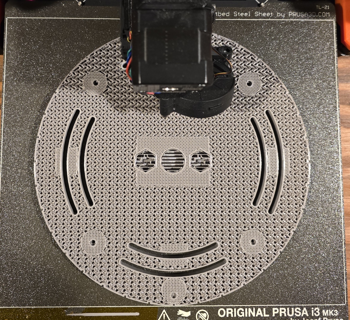
Something I've been searching for is an answer to the question "After the 1st layer, is there any advantage when I'm having the corners lifting to changing the build plat temperature from 90 C up or down by 5 or 10 degrees to help minimize the thermal stress ?"
Er, the only correct answer to that is - sometimes.
Increasing the temperature can help but the offset is increased elephant's foot and loss of detail in the first layer.
Increasing the temperature after the first few layers is more useful but you will find it already implemented in many presets.
Cheerio,
RE: PETG corners of prints bending up at around the 1.3mm of thickness
Ok on "sometimes". It's the nature of tweaking anything.
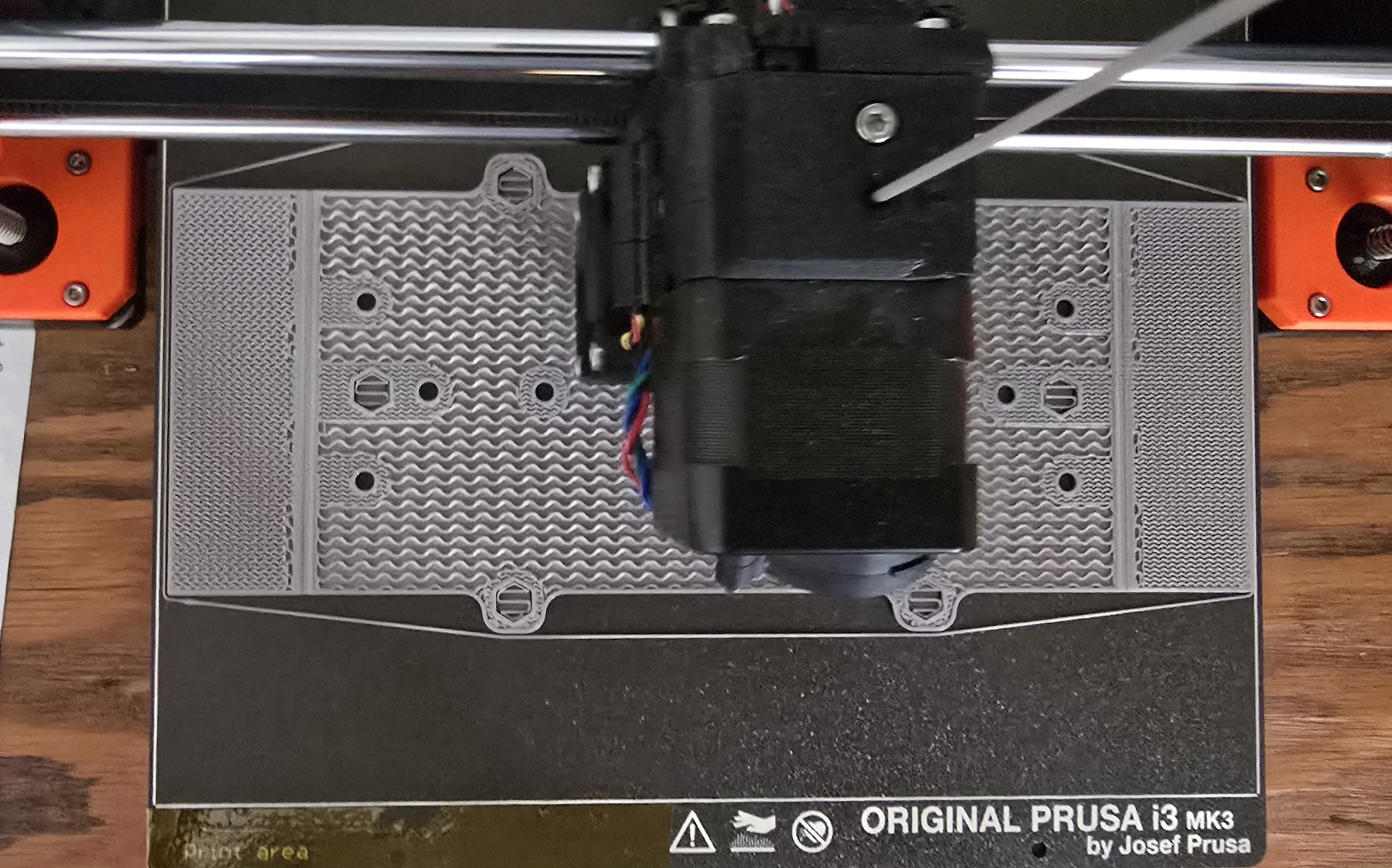
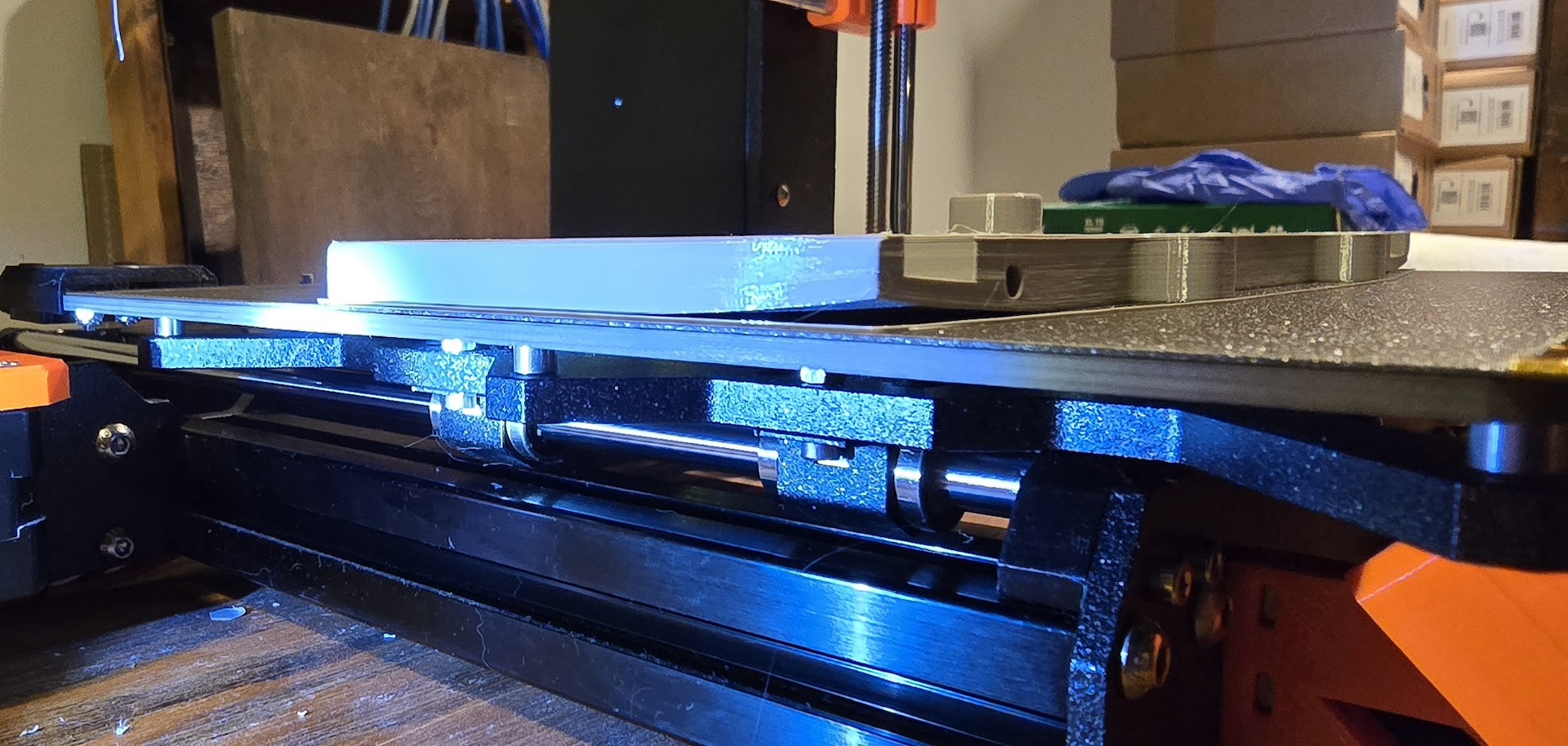
I printed the bottom bracket yesterday. Enclosed is the picture half way through. I added the disk helpers on the corners. Instead of a 50 % fill along the entire left and right side, I just added fill at the stress point on the corner. When this whole assembly is on a piece of 2x4 wood, there are either metal straps or nylon Tie Wraps holding the upper piece and this bottom bracket together. The extra fill is at the corners of this. There are also side pieces, and they have been printed with 50% fill on their corners. They are not as thick (5 mm), so they print OK.
The holes where a screw can be used are 50%, but they are round and distributed on the interior.
After the 1st layer, I brought the bed temperature up from 90 to 93. Thanks to your comment, I'll do that step after the 3rd layer.
Today I print the bottom section again. It will have similar fill and support pads on the edges. The structure is similar to this piece, the difference being that it is a full rectangle and a bit higher (10 mm vs. 5 mm). I'll bring up the bed temperature to 93 at layer 3. I will post on how that goes. If it fails, I'll do a destructive test to determine if I can back off the fill to 30% or so and also try a larger size "Lilly Pad"/support disk.
RE: PETG corners of prints bending up at around the 1.3mm of thickness
SUCESS ! using a similar setup to what I used on the underside piece, I got a good print with no pull-up.
I put the "lilly pad" disc on the corners. It's easy to cut them off with a sharp Xacto knife. Instead of the 50% fill on the entire left and right sides, I just had a bit where there will be maximum compression on the piece when either metal or Tie Wraps hold the assembly on to the wooden 2x4. As soon as the base layer was down and the fill started, I took the print plate tempurature up from 90 to 93 degrees.
I suspect that, as has been pointed out by Diem, that 50% might be a bit too aggressive. I put in a strip at 30% so I could see what 20, 30 and 50% look like. I'm thinking that the 50% does have the "give" needed to handle the thermal compression forces as the piece cools down.
This also got me thinking about how much like concrete and wood, one has to think about if the pieces is in compression, extention or a beam. Where I have the 50 % now, that is an area of compression. In the piece that failed, where the entire side was 50%, it was acting more like a beam and the 50% pulled more as the piece cooled down. Where the screws are, the piece is more in compression so the 50% around each hole increases the strength. Having started out with 3D printing making chassis for PCBs, there was no need to worry about all this. The dish holder was a very different project.
Thanks to all who helped, I hope this post will help others. Below is a pix of the final fill strategy.