Adjustments for y axis
Hey i got a Prusa I3 MK2 and adjusting the y axis shafts. Im taking some slop out of the bearings by moving the shafts outward. What is the correct dimension across the 2 shafts from the outer diameter from each shaft. Im around 7.025" or 178.44mm. I dont want to mush pressure on the bearings but just enough to take the slop out. I have all cnc machines and want to adjust this as close as possible. Thanks.
Re: Adjustments for y axis
The y shaft centres should line up with the centres ou the two slots in the lower edge of your main frame.. to allow for manufaccturong tollerances and the fact that most builders dont have measuring tools ot that size. The setup process guides you to use the frame as a go. Nogo gauge. Negating the need for acurate measurement!
There is a diagram of the frame somewhere on the forum. But i have never used it.
Regards joan
I try to make safe suggestions,You should understand the context and ensure you are happy that they are safe before attempting to apply my suggestions, what you do, is YOUR responsibility.Location Halifax UK
Re: Adjustments for y axis
🙂 this is not the dimension from front to back from side to side im looking for. By giving the bed a little tension there is no noise from shaking. My concern is over time the bearings will wear on the sides more than evenly.
Re: Adjustments for y axis
Hi Miniz.
Please see the attached Diagram.
I can understand that altering the front to back dimensions of the threaded rod frame, will not affect the quality of the Y axis bearing fit at all.it will simply reduce or increase the potential Y axis travel distance, reducing the length too much will cause restricted Y axis travel and result in lost steps.
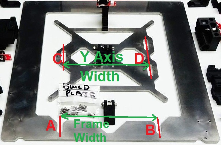
I thought you were hoping to change the width between the Y axis smooth rods, to reduce the free movement in the bearings, perpendicular to the Y axis smooth bearings. the smooth rod centre dimensions are governed by slots A and B, above. in a normal build, the bearing location is controlled by slots C and D in the Y axis platform.
I believe what you want to achieve, is to change the relationship of the Y axis Width and the frame width as shown above, so that the bearings are 'pre tensioned' across the frame to eradicate some of the 'free play' in the bearing fit.
The bearings on the Y axis platform are retained by Zip Ties, which are intended to allow a small degree of self alignment of the bearings.
if you want to experiment with pre tensioning the bearings, you could consider removing the Mk42 heatbed, if it's fitted, and cut one zip tie on the bearing in Slot C, then insert a 'shim' or spacer between the bearing and the side of the slot, on only one side of the slot... this will slightly raise the bed height on that side... but you can feel the difference in the bearing fit, without actually making an irreversible change to the kit...
Once you find the approximate change that you would like to implement, you can lift off the Y axis platform and either add shims to say the outside of Slots C and D, or machine out slots C and D by half of the shim thickness, ( say the left hand side of 'C Slot' and the right hand side of both 'D slots' ) this will have the effect of slightly raising or lowering the build platform, overall but MAY give you the preload you are looking for...
beware that lowering the platform too much may cause the Mk42 Hotbed screws to collide with the frame, in my case there is very little space on one side. (Raising the hotbed might restrict the Z height by a tiny amount... Right at the top, my X carriage sometimes catches the filament holder parts where they wrap under the frame..
I think adjusting the platform would cause a lot less work, than trying to adjust the Threaded rod assembly...
Regards Joan
I try to make safe suggestions,You should understand the context and ensure you are happy that they are safe before attempting to apply my suggestions, what you do, is YOUR responsibility.Location Halifax UK
Re: Adjustments for y axis
So glad I looked for "178" in this forum!
Neither the book nor the online assembly instructions makes it clear that the 178.x mm measurement shown in the video is necessary. This last post and the diagram clarifies that the reason is to align the carriage with the y-axis stage.
Thanks
Re: Adjustments for y axis
My pleasure John. We can all read.the same build information and see different things.
Often the same information presented diferently, can be understood easier.
Regards joan
I try to make safe suggestions,You should understand the context and ensure you are happy that they are safe before attempting to apply my suggestions, what you do, is YOUR responsibility.Location Halifax UK