Z-band issue in one area of print
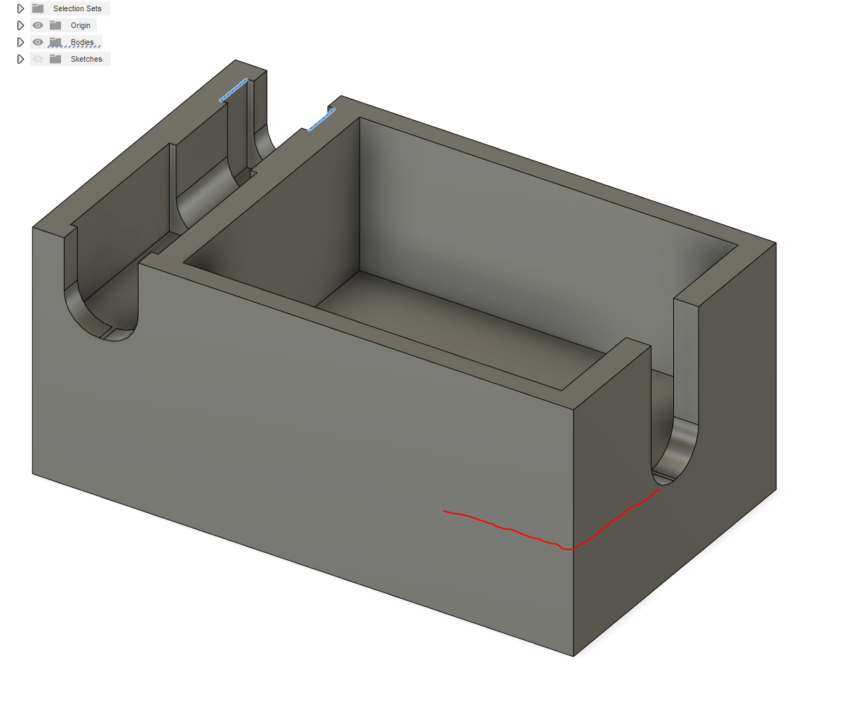
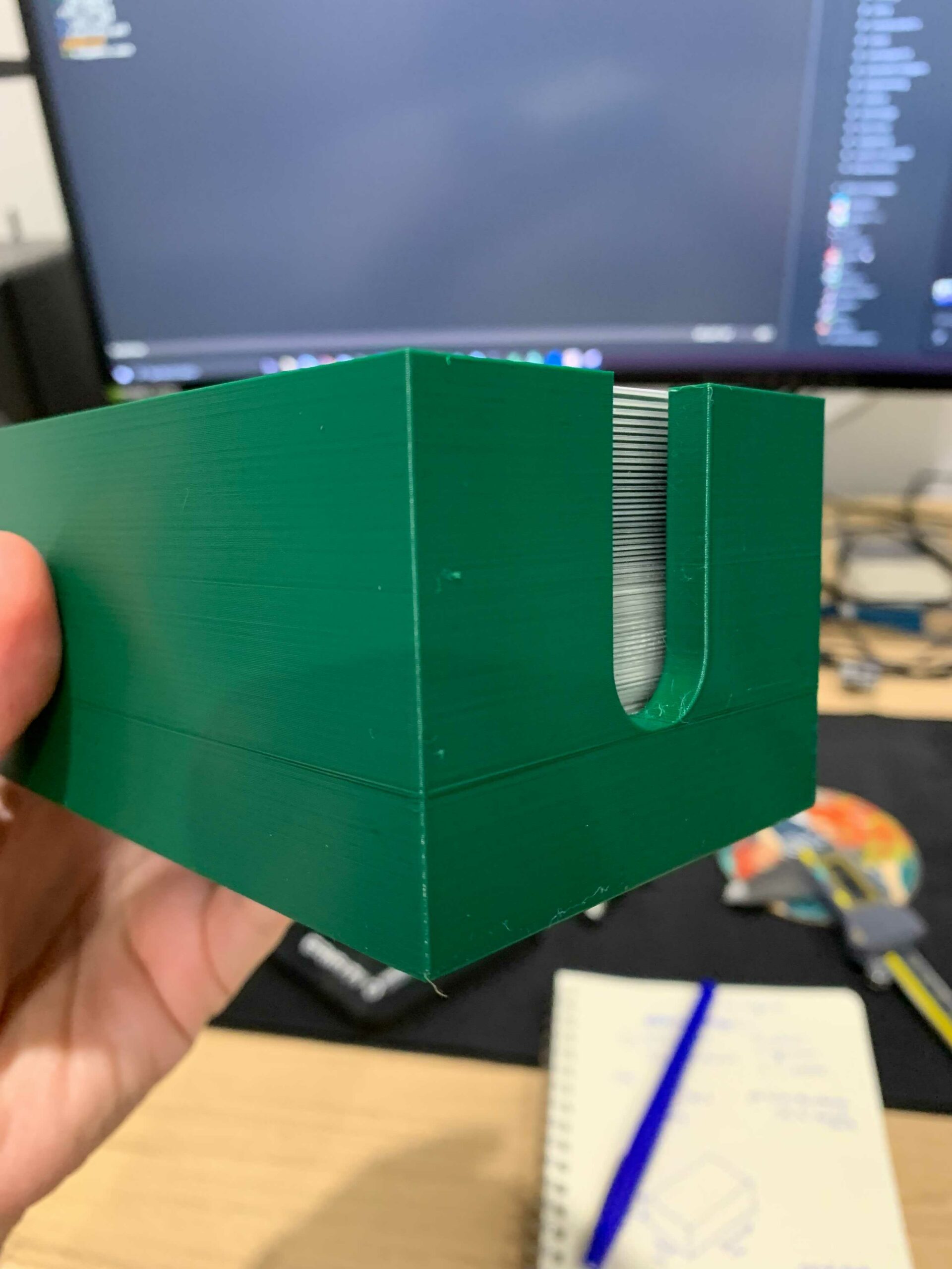
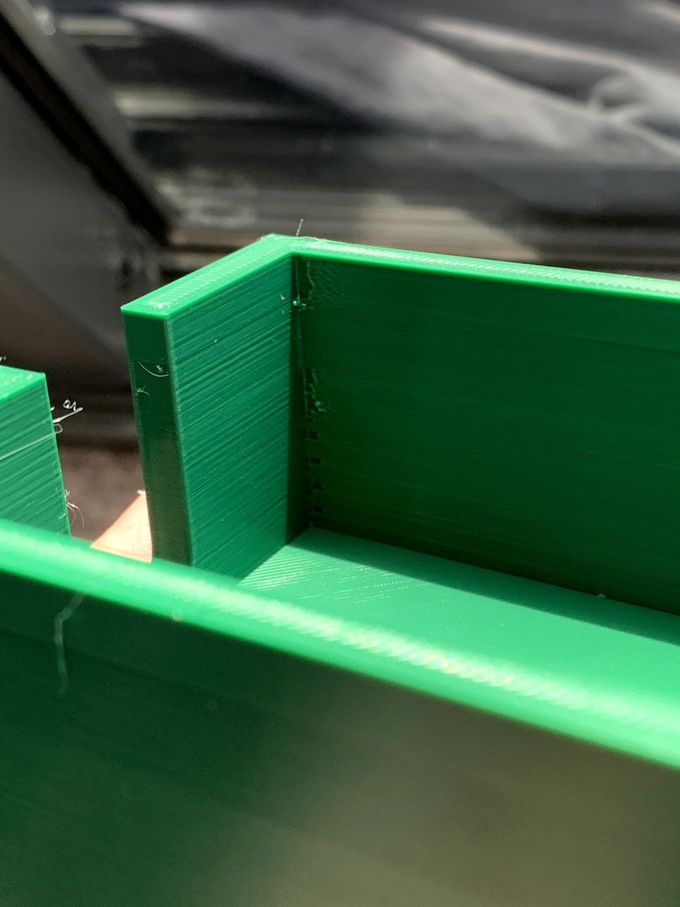
Hoping someone might be able to help me out with this print. I'm having an issue where I get a z-band that aligns exactly with a flat plane area on my print. Any idea what setting I might need to change to address this?
I have both the bondtech hotend and extruder upgrade.
Any help would be much appreciated!
Band
Is that band where the sides meet the solid bottom?
--------------------
Chuck H
3D Printer Review Blog
Z-artefact
Yep at exactly that spot. My friend suggested I enable the option to print the perimeters first and increase perimeters to 3 so I'm trying that now. Will report back.
Search for the term "buldge"
-
Between solid infill and sparse infill.
-
Between sparse infill and gap fill
-
When the number of perimeters increases or decreases between layers.
-
Be sure you're not just seeing the effect of minor warping/lifting/curling along edges or in corners. This can really throw troubleshooting off. Rotate the print and verify the problem occurs in the same place.
-
Slow down external perimeter speeds (and all speeds in general). If the nozzle is moving a bit too fast, you get slight under extrusion on some layers. These are apparent as adjacent layers print with slightly different extrusion rates. I use 25mm/s for external perimeters when appearance is important.
-
Calibrate your extrusion multiplier for each filament. Any slight over or under extrusion can produce very small but noticeable variations in layers with different features (e.g. infill, gap fill, top solid infill). The closer your slicer settings match your actual printer and filament, the more accurate the gcode will be.
-
Calibrate linear advance (LA) for each filament. LA adjusts the flow of filament to compensate for acceleration and deceleration. If it's not right, you may see artifacts even away from features such as bumps or hole on the same layer. In some cases, a hole on one wall causes imperfections on the far side of the print.
-
Add an external perimeter if vertical walls allow it. The thicker combined perimeter allows the filament flow to even out.
-
Tweak perimeter extrusion widths. The problem can appear when the slicer switches between gap fill, sparse infill, and solid or top infill. If you can find a multiple of perimeter widths that minimizes these transitions, it can work for a specific print.
-
If you are the part designer, make vertical free-standing walls thicker. IME, at 1.5mm thick, the problem is less noticeable. You can try for a multiple of extrusion widths, although be aware the PrusaSlicer does some internal calculations for overlap between extrusions that can throw you off.
-
Check cooling. Variations in fan speeds can cause changes in print appearance.
RE: Follow the directions
@Bobstro is dead on. This is a common problem caused by the change from a solid base to walls in PrusaSlive.
--------------------
Chuck H
3D Printer Review Blog
Th
@bobstro thankyou for your incredibly detailed post!
Can confirm that using 3 perimeters and external perimeters first did not help, and made a weird defect on the inside of the print.
I did calibrate my extrusion multiplier for this filament some time ago but I might give it another shot, i'll also try decrease the external wall print speed.
Quick and simple test by reducing speed
[...] i'll also try decrease the external wall print speed.
One of the quickest and simplest diagnostic tests is to simply dial the print speed back 50% using the front knob mid-print. If that improves your surfaces, you know you can make some simple slicer settings changes to improve print quality.