Relay on GPio or is it passthrough
Goodday, i need to switch an (house ventilation) fan on when the printer starts a print (and switch off when ending)
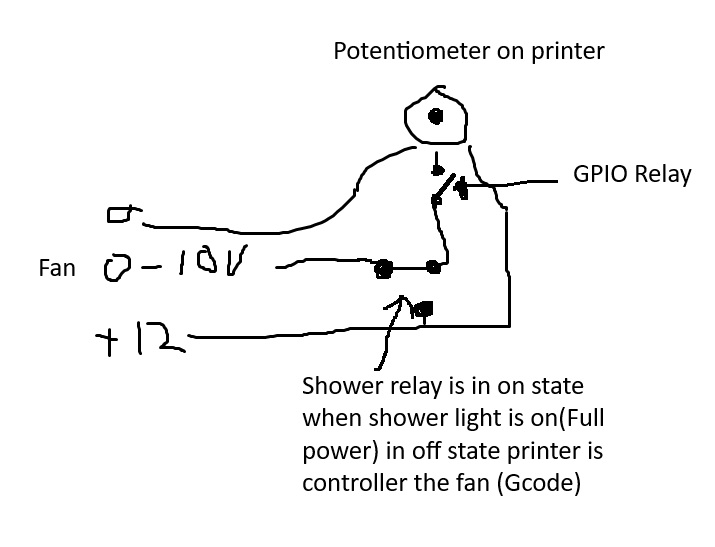
The fan is controlled by an potentiometer for fan speed on the printer. I plan to switch/cut the signal line because the signal is also controller elsewhere (Shower lights switch it on through relay)
The fan is controlled by an 12v signal that gets manipulated between 0-12volts (Yes input is capable of 14volts) through an potentiometer. (It is also switched directly to full power by an relay from the shower lights)
Do i need to hook up an relay to the GPIO outputs or can i use the internal transistor? I don't understand the pull-up resistor things and i know when 3.3v will be floating on the 0-10volt line the fan will always be in 30% mode which is not ideal.
And does the wattage/amps of the coil of the relay matter?
Thank you in advance
RE: Relay on GPio or is it passthrough
Ooh and is the relay input stopped when i stop an print mid-print. There will be no running an end g-code by then.
Or is it stopped when the printer is reset / turned off?
The reason i am asking is because when the fan stays on the complete house gets ventilated and it will be very cold after a day or so 😂
By the way, this is the setup:

RE: Relay on GPio or is it passthrough
Personally I wouldn't introduce a galvanic connection without very good reason. It will work but more "interesting" things can happen. I prefer my electronics boring.
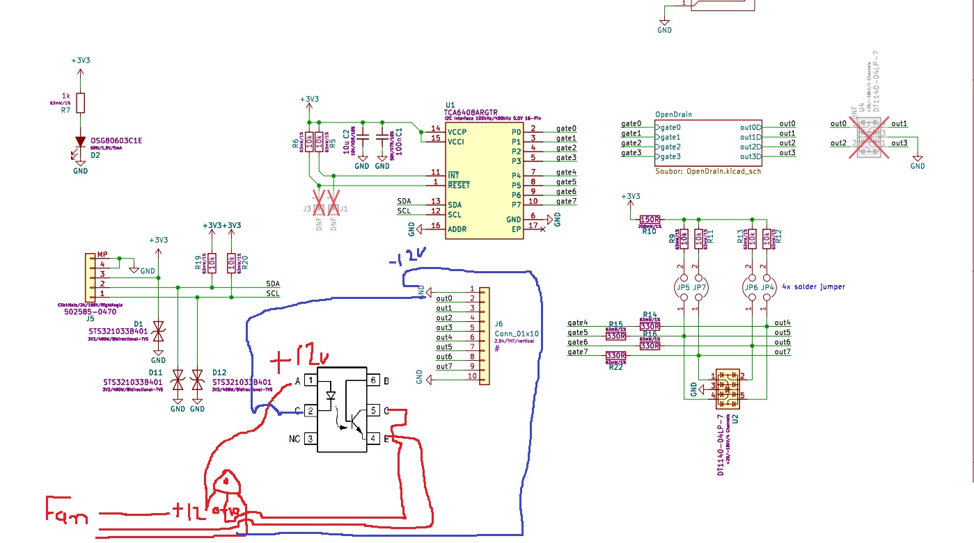
How about a CNY17 optoisolator? Drive the LED (pin 1,2 ) via e.g. 1 kOhm from the GPO. Put the collector (5) to +12V (sourced from the fan side, not the printer) and hook up the poti between Emitter (4) and GND, the slider to the fan's control input. I'd expect a poti in the low kOhm range.
If you experiment with a relay, be sure that it has a built in reverse diode because the coil is capable of generating fairly high voltages when turned off / disconnected.
Datasheet:
RE:
I was thinking of an idea like this. But my knowledge stops after: The transistor switches out 1-2-3-4 to ground in the gpio. It says 30V/1A/400mW/190ohm. (I always play safe and try to pull way less then that)
Where does the thing (pin 1 or pin 2 from optocoupler led/relay coil) it switches gets it + power from then?
Then comes the pull-up resistor story which i need or don't need?

I am now looking in to an reed relay. If the coil would be 3.3.v it can switch the 0-10v line and it won't alter the signal. I am aware this / an relay will inflickt some inductive coil spark. 😊
RE: Relay on GPio or is it passthrough
This person uses an relay that has an extrae wire on the coil side to switch an transistor on which then switched the coil on.
Anyway this seems all too overdone for an simple 12v signal switch. (i did not measure the current flow but it i suspect it to be very low.
I like the optocoupler idea. But then again there is an internal transistor in it (same as in the gpio maybe?) and i simply do not really understand these things.
RE:
The trick with the optocoupler is that the phototransistor gets its base current optically, so the LED side and the phototransistor side can be at different electrical potential.
But yes, it's more complex than necessary if galvanic isolation is not required.
You're showing the schematic of the GPIO board's outputs. The most straightforward way to use it would be to let the output pull the slider of your potentiometer to GND via (e.g.) a 100 ohms resistor to protect the transistor (it's not safe to connect it directly to 12 V which would happen if the poti is turned all the way).
That is, when the "gate" signal goes high, the transistor becomes conductive and voltage at the external port (pin 6) drops to zero volts, more or less (see Fig. 1 in datasheet for VGS=3 V. It's very close to 0 V when the current through the pin is just a few mA. This just for background info, if interested in what the board does).
RE:
Ok to wire the CNY17 like this? They have the cny17-3 in stock in a local shop here i think.

Or rather this way?
I don't know if the optocoupler led can run on 12v? should there be an resistor between +12v?
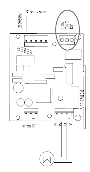
This is normally running on the +12v from the fan: It is an automatic hygro sensor.

RE: Relay on GPio or is it passthrough
Your last sentence:
That is, when the "gate" signal goes high, the transistor becomes conductive and voltage at the external port (pin 6) drops to zero volts, more or less (see Fig. 1 in datasheet for VGS=3 V. It's very close to 0 V when the current through the pin is just a few mA. This just for background info, if interested in what the board does).
Gate signal drops to 0V / ground of he gpio PCB?
You mean it is not an switch between pin 1 gnd and ouput pin 2? But an switch to pcb ground and output pin 2? But when it does that there als has to be an voltage supply somewhere of 3.3v? How else would you be able to switch something with this thing.
I would have prefered a more simply design with an 12 / 24v supply and switches/relays. 😢
RE: Relay on GPio or is it passthrough
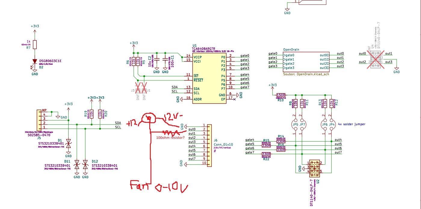
I think you mean this in with only the wiper being pulled down.
But this way the transistor would need to be in "on state" most of the (non printing) time. But only during printing it needs to be switch off to not manipulate the potentiometer output.
RE: Relay on GPio or is it passthrough
I had similar idea but decided to not hook anything to the gpio directly on the board. Instead I went a bit more complex route - HomeAssistant on Raspberry Pi + esphome to control relay for fans and lights, then I added the printer to the same network as raspberry pi and esphome, added Prusa printer to the Home Assistant as integration and added automation to control relays depending on the fact if the print is printing or not (with a bit of delay).
This also makes it easier to extend to other devices and talk to the printer via HTTP over local network only, no direct electricity invovled.
See my GitHub and printables.com for some 3d stuff that you may like.
RE:
Well an simple how to switch this or that on or off -manual would be helpfull.
I have an feeling a relay is way too much for what i am trying to achieve here. I have also seen an mosfet option for leds, but then again i don't know how that works.
Even tapping into the advanced filtration fan connector is not an option because it is PWM controlled. I can hook it up to the nozzle heater? probably 24volts. haha Just kidding.
But when it comes to pcb's i can only identify the most parts, not tell you how the operate.
An schematic of an simple relay option would have saved me seaching for 6 hours today. and i still cannot go to the shop to pick up the stuff.
RE: Relay on GPio or is it passthrough
The CNY17 A- and K- pins are just a LED so you can't apply 12 V directly or it'll burn out.
The GPIO board provides already a MOSFET (to GND) so you can use it to leave any signal untouched or pull to GND.
Whatever option you chose, be sure you have a clear understanding how it'll work before applying power.
RE: Relay on GPio or is it passthrough
So you mean the gpio mosfet is able to switch the 0-10v signal without any further resistors or other thingys?
Just connect fan side 0-10v signal input to ground connection gpio; and output 0-10v from potentiometer to open drain -0?
If you need to ask all these questions: don't try it.
Cheerio,
RE: Relay on GPio or is it passthrough
>> So you mean the gpio mosfet is able to switch the 0-10v signal without any further resistors
The mosfet will robustly pull the pin to 0 V but there needs to be some resistor towards supply voltage (that pulls it up so the mosfet can then pull it down). If you connect it directly to 10V or 12V and then turn on the MOSFET, it will break.
For example:
- +12V via a 470 ohms resistor to first potentiometer terminal (let's say, a 47 kOhm poti)
- second potentiometer terminal to GND
- GPO to potentiometer slider
- fan to potentiometer slider.
This way you can adjust the voltage freely between 12V (in reality 11.9 V - close enough) and 0 V. If the mosfet is active, the fan sees 0 V (maybe 0.05 V in reality).
RE: Relay on GPio or is it passthrough
Ok. I am really sorry for all the questions. I am not alone on this one. I see on the gpio product page many many questions.
I understand. But the mosfet should then be active when the printer is off.
That is unfortunatly not the solution. If i stop an print and shut down the printer the fan will keep running right?
I think the optocoupler is an nice solution.
If i drive the optocoupler led by the gpio's 3.3v and an 220ohm resistor (10mA 1.4v led) and the minus- side to an open drain to gnd port this is able to drive it?
On the other side it just cuts the 0-10v signal. Even when printer power is off. 😁
Thank you for your time.
RE: Relay on GPio or is it passthrough
> That is unfortunatly not the solution. If i stop an print and shut down the printer the fan will keep running right?
That's why it's better to have a separate system that do not rely on the printer executing commands, especially if it ends in error.
I would rather recommend smart socket.
See my GitHub and printables.com for some 3d stuff that you may like.
RE: Relay on GPio or is it passthrough
The state of the open drains goes to off when the printer is shut down right?
If not then the only helpfull thing is an relay. Which does not work without power, but will be activated again upon boot. 🫠
RE: Relay on GPio or is it passthrough
So an little follow up.
I went to the electronics store. The helpfull man told me when i used an optocoupler this would essentially give me the same switching.
He told me the gpio is possible to directly switch the ground of an 24v reed-relais. It is 24v 1A so that is more than enough.
I bought the sil24 1a72 71l reed relay and hooked it up to the psu for testing and it works.
I will report back when gpio arrives
RE: Relay on GPio or is it passthrough
Does anybody know if the gnd point on the gpio is an solid 24v- ground?