RE: XBuddy board GPIO?
True. I looked at the Mini (since it should be more similar to the MK4 than the MK3 is), and the schematic shows Conn_01x10 on page 11. It appears it's got several inputs to the STM32 micro that are not connected to anything. PE0, PB5, TX_1, RX_1
Additionally, SCL and SDA are on this connector, though these two are shared with other things. The first 4 only connect from the micro to the connector.
I will look for unused connectors once I get my MK4 and see if they are labeled on the silkscreen, once I get that. And I won't have time for at least a few days, but I could test one of those signals on my MINI to see if it works with the "wait for pin state" gcode.
RE: XBuddy board GPIO?
@jseyfert3 Thank you for looking into this for me. I really appreciate it!
At least on the Mk3, I think I've found two unused pins on plug 3. I2C pins SCL and SDA (pins 6 and 8 on plug 3) aren't used, on the Mk3S/+. Unfortunately, according to this, Prusa doesn't support I2C referencing G-code, so you would have to address them as digital pins PD0 and PD1, which have hardware pull-up resistors, so the arduino would have to pull them down ONLY. There might be some unused pins on the LCD connectors, but I'm not sure.
If I could get an analog (PWM) output and a single digital input, it would allow me all the functionality I need. M42 would let me set a PWM output that corresponds to a temperature. Use a sufficiently sized filter cap, and have the arduino read the voltage, to establish the target temperature. Drive the heat bed to ~120C, then use M226 to wait for the arduino to signal that it's reached operating temperature.
It wouldn't be perfect, because PWM to analog to ADC won't be exact, for temperature, but if my minimum temperature is ~29C (~85F ), and my max temp is 42C (~108F), then resolution would be pretty good on a 0-5V signal (19.6mV per LSB, giving .05° C per LSB)
Just... need to find a couple open pins.
RE: XBuddy board GPIO?
WHY WON'T IT LET ME EDIT?!
anyway. Still on the Mk3, I'm pretty sure that plug 2, pin 1 (and pin2, but that's a ground) aren't connected to anything on the LCD board. This means that PE3 should be available as a PWM output.
Now, if only I had the schematics for the Mk4...
This is assuming that any of the pins will trigger the completion of the M226 "wait for pin state" G-code. I eagerly await your test results!
RE: XBuddy board GPIO?
My MK4 arrived. I'll take a look at the xBuddy board pinout tonight or tomorrow night.
RE:
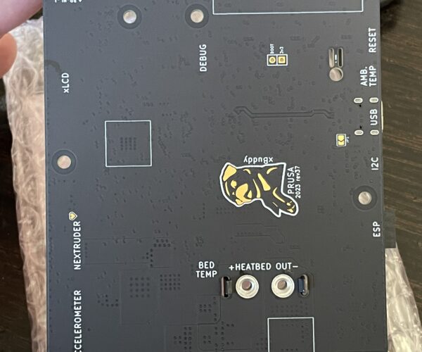
The xBuddy, rev37, does not have the Open Source logo, or any text stating it’s open source. I’m worried this may indicate Prusa’s intention to not open source the schematic for the MK4…


I also was pointed to a blog post from Adafruit (which is open source everything) was pointing out all these companies that started open source, exist because they were open source, and began or completely went closed source. They included Prusa, and even interviewed Josef Prusa. He said he will give an update in a couple of months with what they decide to do. His replies in the article seem to indicate Prusa is no longer open source, the only outstanding questions are what isn’t open source anymore, and what that means for stuff that’s not. It seems they are planning on having some sort of info by request with license agreement, instead of open source.
This is very sad to me. With my Mini I thought it was so cool that I ran an open source OS (Linux) on my computer, open source CAD (FreeCAD), open source slicer (PrisaSlicer) and printed on an open source printer (Mini+). With my MK4 it appears the open source 3D printing chain is now broken…
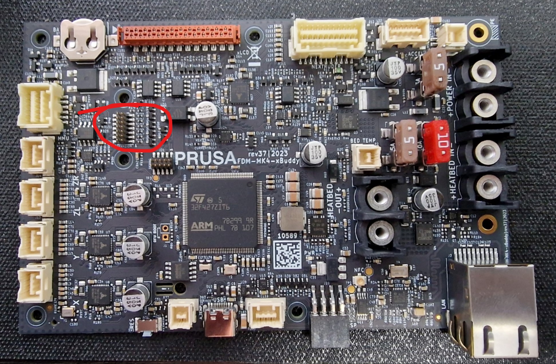
Anyway, to the topic at hand, what caught my eye was a double row of header pins labeled “Expansion”. I haven’t gone though the full build yet, nor the instructions, so it’s unclear if this is used, but just from the name I would say not. I’d bet it’s for future expansion and would contain at least 1 GPIO pin.
I will contact support and see if I can get info on this.

RE: XBuddy board GPIO?
The expansion slots are not used, per the wiring checks on chapter 7, step 54 of the assembly instructions, the final check before covering the xBuddy box.
RE: XBuddy board GPIO?
Just got off chat. Support said they don't have details on that yet, but it should be open sourced soon. I asked if it would actually be, given the board in the assembly instructions has the open source logo, but my own board does not. He said it "It will be for sure. We are actively working on that."
RE: XBuddy board GPIO?
Yup. I remember an interview with Josef Prusa, shortly after the announcement, where he said that they WERE going to release it as open source, but they were still working out the details of which license to release it under, and how to enforce that license. For you and me, it won't make a difference, but I think they are trying to prevent other companies from profiting from THEIR work, without some form of compensation, which I totally can understand. Prusa put a lot of work into that board, and to have a chinese manufacturer start making the whole thing for 1/3 the price would undercut their entire incentive to create new things.
I am guessing that the "expansion" port is primarily for the MMU3, but I'm hopeful that there are at least 2 unused GPIO, one of which being analog out, which would let me do what I'm wanting.
Then it's not technically open source, but yeah, if they release it under some different license (CC BY/NC/SA) then yeah it won't make a difference for you and me, and we'll still have the schematic.
It doesn't stop manufacturer's from making knockoffs though. Heck, even not releasing the schematic at all doesn't mean much, as with enough resources (like chinese manufacturer's would have) you can reverse engineer it. Not releasing the schematic under any means would me you and I would struggle to do what we're discussing though.
So perhaps not being open source, but still releasing it just under a license, is the way to go? Who knows...it's a complicated topic for sure.
On topic, I don't think the expansion port is for the MMU. The top row of white connectors, the larger one on the right? That is labeled MMU. So if they have a dedicated connector for MMU I wouldn't think they'd need to plug that into the port labeled expansion port.
I'm thinking expansion is just for any future add-ons they want to do. For example, they planning a Smart Box for the enclosure, which will have smart RGB LEDs, electronic lock, RFID reader, advanced temp sensors (whatever that means), humidity sensor, and microparticle sensor. Though it would be easy to run all that through the I2C bus too.
Always good design to leave some extra stuff though, so if things change it can be added as a retrofit instead of requiring a new board.
RE: XBuddy board GPIO?
On topic, I don't think the expansion port is for the MMU. The top row of white connectors, the larger one on the right? That is labeled MMU. So if they have a dedicated connector for MMU I wouldn't think they'd need to plug that into the port labeled expansion port.
I'm thinking expansion is just for any future add-ons they want to do. For example, they planning a Smart Box for the enclosure, which will have smart RGB LEDs, electronic lock, RFID reader, advanced temp sensors (whatever that means), humidity sensor, and microparticle sensor. Though it would be easy to run all that through the I2C bus too.
Always good design to leave some extra stuff though, so if things change it can be added as a retrofit instead of requiring a new board.
That's very interesting indeed. That leads me to believe that they might actually have some significant open GPIO on that connector, which would be fairly easily used for enclosure temperature control/feedback. Thank you!
RE: XBuddy board GPIO?
Also I have not forgotten about testing the wait on pin status gcode on my mini. It’s just work is getting a bit busy, I have too many projects, and assembling my MK4 and enclosure are higher priority in my free time than testing pin status on the mini.
But once that settles down, I will test the pin status gcode on my mini. I was originally going to sell it, probably still will, but I decided to wait until more of the MK4 bugs are worked out.
I just learned about 4-axis 3D printing, and if it was an MK3 I would have kept it and attempted to convert to a rotating 45° nozzle 4-axis printer. You can print 90° overhangs with no supports and no structural or finish issues.
I’m thinking if Prusa wants to stay in the lead, they should be the first to release a commercial 4 or 5 axis FDM printer…
RE: XBuddy board GPIO?
The enclosure does not carry OHW logo, yet the sources were published couple days ago.
The xBuddy, rev37, does not have the Open Source logo, or any text stating it’s open source. I’m worried this may indicate Prusa’s intention to not open source the schematic for the MK4…
I also was pointed to a blog post from Adafruit (which is open source everything) was pointing out all these companies that started open source, exist because they were open source, and began or completely went closed source. They included Prusa, and even interviewed Josef Prusa. He said he will give an update in a couple of months with what they decide to do. His replies in the article seem to indicate Prusa is no longer open source, the only outstanding questions are what isn’t open source anymore, and what that means for stuff that’s not. It seems they are planning on having some sort of info by request with license agreement, instead of open source.
This is very sad to me. With my Mini I thought it was so cool that I ran an open source OS (Linux) on my computer, open source CAD (FreeCAD), open source slicer (PrisaSlicer) and printed on an open source printer (Mini+). With my MK4 it appears the open source 3D printing chain is now broken…
Anyway, to the topic at hand, what caught my eye was a double row of header pins labeled “Expansion”. I haven’t gone though the full build yet, nor the instructions, so it’s unclear if this is used, but just from the name I would say not. I’d bet it’s for future expansion and would contain at least 1 GPIO pin.
I will contact support and see if I can get info on this.
RE:
Leaving the OHW logo off is them covering their own ass. They're dealing with the lawyer effect: Can't get sued (can, but it won't hold), if they don't tell you it's open source, but release the source. If they put the OHW log on it, but the source isn't in the wild, then SOME people might get butt-hurt enough to call a lawyer. Stupid that it's necessary, but I can't fault them for playing it safe.
BACK ON TOPIC:
Looking at the pics you posted, I'm seeing a separate connector for both the MMU and the (technically unannounced) accelerometer add-on, so I am REALLY hopeful for a couple of pins to play with, to do chamber temperature control. Probably should start working on the actual hardware design and arduino code, regardless.
RE: XBuddy board GPIO?
My comments were mostly because the image of the xBuddy board in the assembly instructions, dated 2021 (so an early prototype?) has the OHW logo. That seemed to imply it originally was on the design, but removed at some point, since the board I got didn’t have the logo.
While you’re here, is there any chance we could get info on if there’s extra GPIO pins broken out on the expansion pins or elsewhere? I asked support and all I got was they were working on open sourcing the schematic and they had no other info. We don’t need the schematic to try to do what we’re trying to do in this thread with enclosure temp control, just a spare GPIO pin that we could use with the “wait for pin status” g-code.
The enclosure does not carry OHW logo, yet the sources were published couple days ago.
The xBuddy, rev37, does not have the Open Source logo, or any text stating it’s open source. I’m worried this may indicate Prusa’s intention to not open source the schematic for the MK4…
I also was pointed to a blog post from Adafruit (which is open source everything) was pointing out all these companies that started open source, exist because they were open source, and began or completely went closed source. They included Prusa, and even interviewed Josef Prusa. He said he will give an update in a couple of months with what they decide to do. His replies in the article seem to indicate Prusa is no longer open source, the only outstanding questions are what isn’t open source anymore, and what that means for stuff that’s not. It seems they are planning on having some sort of info by request with license agreement, instead of open source.
This is very sad to me. With my Mini I thought it was so cool that I ran an open source OS (Linux) on my computer, open source CAD (FreeCAD), open source slicer (PrisaSlicer) and printed on an open source printer (Mini+). With my MK4 it appears the open source 3D printing chain is now broken…
Anyway, to the topic at hand, what caught my eye was a double row of header pins labeled “Expansion”. I haven’t gone though the full build yet, nor the instructions, so it’s unclear if this is used, but just from the name I would say not. I’d bet it’s for future expansion and would contain at least 1 GPIO pin.
I will contact support and see if I can get info on this.
RE: XBuddy board GPIO?
Slightly off topic, but my connected xBuddy board. 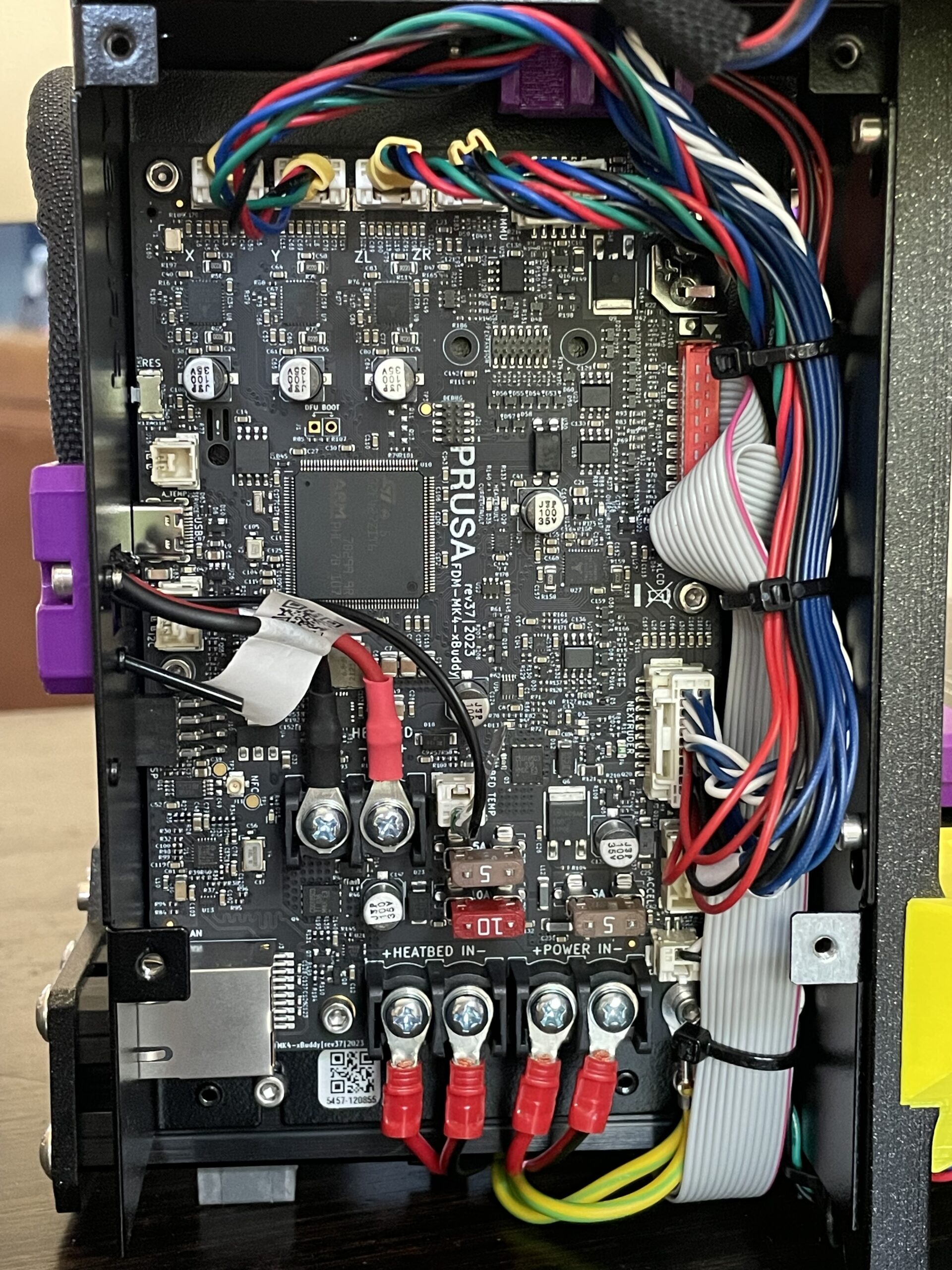
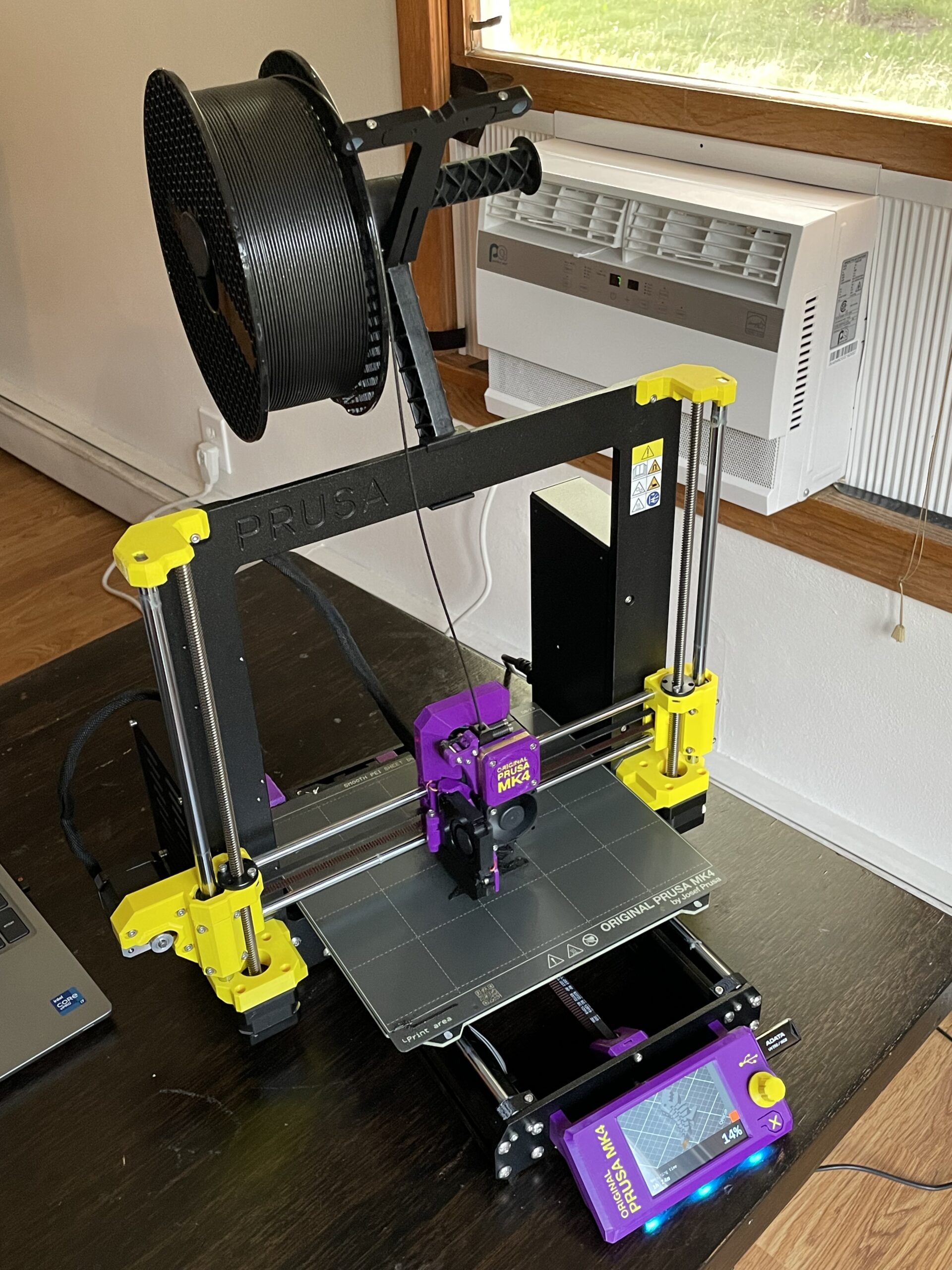
And the completed MK4. Assembly was smooth, besides slightly panicking because a couple of the parts I printed were “behind” the Prusa parts (E4 vs R2, E6 vs E3). They looked the same though. Live chat support cleared it up quickly, version numbers are NOT necessarily the same between the Prusa (E) parts, and Printable (R) parts, and the Printables parts were the latest ones.
Powered it up, all self tests passed, sliced a Flexi Rex for the MK4 in PrusaSlicer and started a print.
Zero issues. Quieter and faster than my MINI+, and I’m running the latest stable firmware, not the input shaper alpha. Excited for the input shaper, though I’ll probably wait to do it until it’s got a stable release.
In the mean time, now that this is built, I’ll try to test the “wait for pin status” on my MINI+ early next week, so that once we know if there is a GPIO pin on the MK4 we can press into use, we’ll know how to do the g-code to use it.
RE: XBuddy board GPIO?
Hi, I've got my Prusa MK4 few days ago and was also looking into a way, how to control lights externally directly from the xBuddy board. The expansion is basically 7 outputs protected by a resistor and BAV99 diode (the SOT23 with marking A7t). I didn't measure it yet (have no time) to see what PIN/if is it connected to MCU directly. If Prusa implemented "M42 - Set Pin State" and "M226 - Wait for Pin State" in their firmware, we should be able to easy add some custom external peripherials to it. The xBuddy has separated connector for all I can think of so there is a chance they might be used by comunity. If someone has time to map what pin goes where would be great.
RE: XBuddy board GPIO?
@jseyfert3: any test results?
RE: XBuddy board GPIO?
Sorry, no. Work got crazy the past couple weeks and haven’t had nearly enough free time for all the things I want to do. Hopefully winding down and I’ll have a chance to poke at it in the near future.
RE:
So no inputs that you saw?
I had the thought to try to map the pins to the microcontroller pins, but poking around with any sort of voltage on the microcontroller pins on a brand new, not even tested board put me off…plus I wanted to build the printer, not test the board. If by winter nobody else has mapped them, and Prusa hasn’t released the schematic, then that would be a great winter project for the days of being trapped inside. But summer just has too many projects and things to do to be spending a lot of time reverse engineering a PCB.
Plus I’ll probably be more willing to have downtime on my MK4 by then. Right now I’ve got too many things I want to print.
Hi, I've got my Prusa MK4 few days ago and was also looking into a way, how to control lights externally directly from the xBuddy board. The expansion is basically 7 outputs protected by a resistor and BAV99 diode (the SOT23 with marking A7t). I didn't measure it yet (have no time) to see what PIN/if is it connected to MCU directly. If Prusa implemented "M42 - Set Pin State" and "M226 - Wait for Pin State" in their firmware, we should be able to easy add some custom external peripherials to it. The xBuddy has separated connector for all I can think of so there is a chance they might be used by comunity. If someone has time to map what pin goes where would be great.
RE: XBuddy board GPIO?
Been doing some digging in the source code. Probably not looking at it right, but here we go. First off, there was a forum post that got me digging:
https://forum.prusa3d.com/forum/postid/656967/
In there, he points at the buddy firmware G-code list, where M226 is defined, and his test shows that it SORT OF works.
I started digging through the code from there. In line 519 of the pins.h library, it looks like the Mini, the Mk4, and apparently something called an IXL all use the same pin scheme, as far as the chip (STM32 ARM Cortex-M4F) is concerned. https://github.com/prusa3d/Prusa-Firmware-Buddy/blob/56a40a0f776bb096468b47f52eb158e0afc84e08/lib/Marlin/Marlin/src/pins/pins.h#L519
I also found that the M42 command is at least defined in the firmware: https://github.com/prusa3d/Prusa-Firmware-Buddy/blob/56a40a0f776bb096468b47f52eb158e0afc84e08/lib/Marlin/Marlin/src/gcode/control/M42.cpp#L41
I am now trying to sort out the PIN_MAP_INDEX, but it looks like the firmware protects the already used pins, so trial and error might be "acceptable"?
Either way, I am cautiously hopeful that there are GPIO pins that are available on the "expansion" header, and that I can write GCODE to both write to them, and listen for feedback on them. In which case, I can do temperature control ENTIRELY in a separate arduino-controlled system, and have build chamber temperature controlled per material, in the slicer settings.