RE: Makign holes for M4 Heat Set Inserts
Sorry for not replying sooner Tango, sleep and then work got in the way 🙂
Have a look at the attached project example. It has cut outs in all directions using the model I pictured above. Note the bridging angles which I did nothing special with, just left it on automatic. While not for M4 the size difference will not cause any difference in bridging in a practical manner.
RE: Makign holes for M4 Heat Set Inserts
Thanks! I figure making the cut-out isn't hard, I just wanted to be sure I didn't get burned by some issue I couldn't anticipate.
RE: Makign holes for M4 Heat Set Inserts
I'm not quite sure what you're describing, but to hold the unit to the wall, there have to be parts behind the drywall and in front that are bigger than the hole made for the unit. So a one piece unit will be a problem
Most items like switch plates are fixed to drywall from the front. Can you do this?
i3 Mk3 [aug 2018] upgrade>>> i3MK3/S+[Dec 2023]
RE: Makign holes for M4 Heat Set Inserts
Most items like switch plates are fixed to drywall from the front. Can you do this?
It has to be either fastened to the wall with screws, and I don't want to use self-tapping screws on drywall - can only put them in and take them out a time or two before the hole they make in the drywall won't hold them in anymore. As I mentioned earlier in the thread, I considered toggle bolts, but I have a friend who is helping me on this and will be crawling through the crawlspace to help me put all this in place. He does HVAC, electrical, and plumbing work (qualified for all three). I've talked about this project with him many times and he has said toggle bolts might work, but his concern is that this wall plate is holding 3" flexible duct on each side, inside the wall itself, and within the room. While that's not a super-heavy item, it's still more weight than a wall box is used to holding. My friend has expressed concern about toggle bolts and the relatively small footprint they have on the drywall, so I'm working with something that will have more of a footprint than toggle bolts or flat "wings" the average wall box has.
RE: Makign holes for M4 Heat Set Inserts
Note the gaps above and below the square nut pocket. Those gaps are #~0.25mm thick. S0 using a 0.2mm layer height it leaves a 1 layer thick patch over the holes automatically when cut out. This means the pocket bridges if the part is oriented such that the screw is vertical. So supports inside the pocket for the nut are not needed. The distance is easily bridgeable. If the screw is horizontal then with classic perimeters the hole is printed open and with arachne it might just do a very thin wall. In either orientation you can just poke through with the screw once the part is printed and the nut has been inserted.
I went over this when you posted it and I've been working on a series of experimental prints on this, t-nuts (which I realize some don't like) and other possibilities. (Part of this is also creating templates to use for screws and nuts and similar hardware so I'll have them all handy in the future.)
I'm now looking this over much more closely and have 2 questions:
- What is Arachne?
- Could you rephrase your reasoning for adding the one layer thick separation on the top and the bottom of the slot for the bolt? I thought I followed what you were saying, but after rereading it closely, I realize I don't, or I don't think I follow it. I'd really like to get it in a different wording so I can think about it from a different viewpoint.
RE: Makign holes for M4 Heat Set Inserts
Prusa Slicer has 2 different slicng methods/engines. There is Classic and Arachne. The Arachne method was originally added to Cura and then later it was also adopted by PS. It is now the default in many Prusa Profiles.
Classic you set your different extrusion widths and if a feature such as a wall isn't thick enough it will not be sliced. So people complain about missing features on their models. It had the detect thin walls option that would artificially try to pick up those 'lost' features but that often ended up causing other issues.
Arachne attempts to adjust the flow down when walls are thinner and increase it when they are thicker. However this also can have issues. Many slicing artefacts are down to the Arachne settings and there are several open issues on github. One of the other problems is that it sometimes also will try to collapse what should be 2 thinner extrusions into a big thick single one. This can cause problems with maximum flow of an extruder being exceeded.
Naturally if you are trying to calibrate extrusion flows then using the default arachne slicing engine is not a good idea, but thats a different topic.
The main take away is that when Arachne is used it can pick up thinner walls in general. Most times that's good and others it is undesirable.
I'm not sure how else I can describe it. Examine the example project I attached and how it slices carefully layer by layer around the holes. The gap between the hole for the screw and the nut pocket, if the cutter for the screw hole and pocket is placed vertically and you do not have a gap then your screw hole will connect to the pocket. This means you now have an unsupported circular extrusion inside a pocket that is almost impossible to access to remove the support that is now required to print that circular feature. Meaning you can no longer get your square nut in there due to that support (or the remains of it). If you don't use support then the hole collapses and you will still have filament blocking the nut pocket.
By leaving a gap that is fractionally thicker than your normal layer height the pocket for the nut has no hole through it and so is bridged, meaning no support required. Easy nut insertion, nothing in the way. As the bridge layer is only 1 layer thick it is easily punched through. Normally you can just screw straight through it into the nut without a problem.
If the cutter for the screw is placed horizontally along the layers then you don't have to worry about an unsupported hole, as its sideways with the layers now. Again examine the previous attached project.
RE: Makign holes for M4 Heat Set Inserts
@Neophyl: Thank you. Yes, that was a major help, both in terms of me gaining a clear understanding of why to use Arachne over Classic and it gave me a clear understanding of just why you use the one layer barrier in your cutouts. Quite helpful and much appreciated!
RE:
One thing I have run into with Arachne, is that it can negate using the "sharp angle" technique as shown here:
https://github.com/gregsaun/maker_cheatsheet/blob/master/3d_printing/techniques.md#sharp-angle
I have used that technique on several models where I wanted a sharp corner, and those are best sliced in classic mode.
RE: Makign holes for M4 Heat Set Inserts
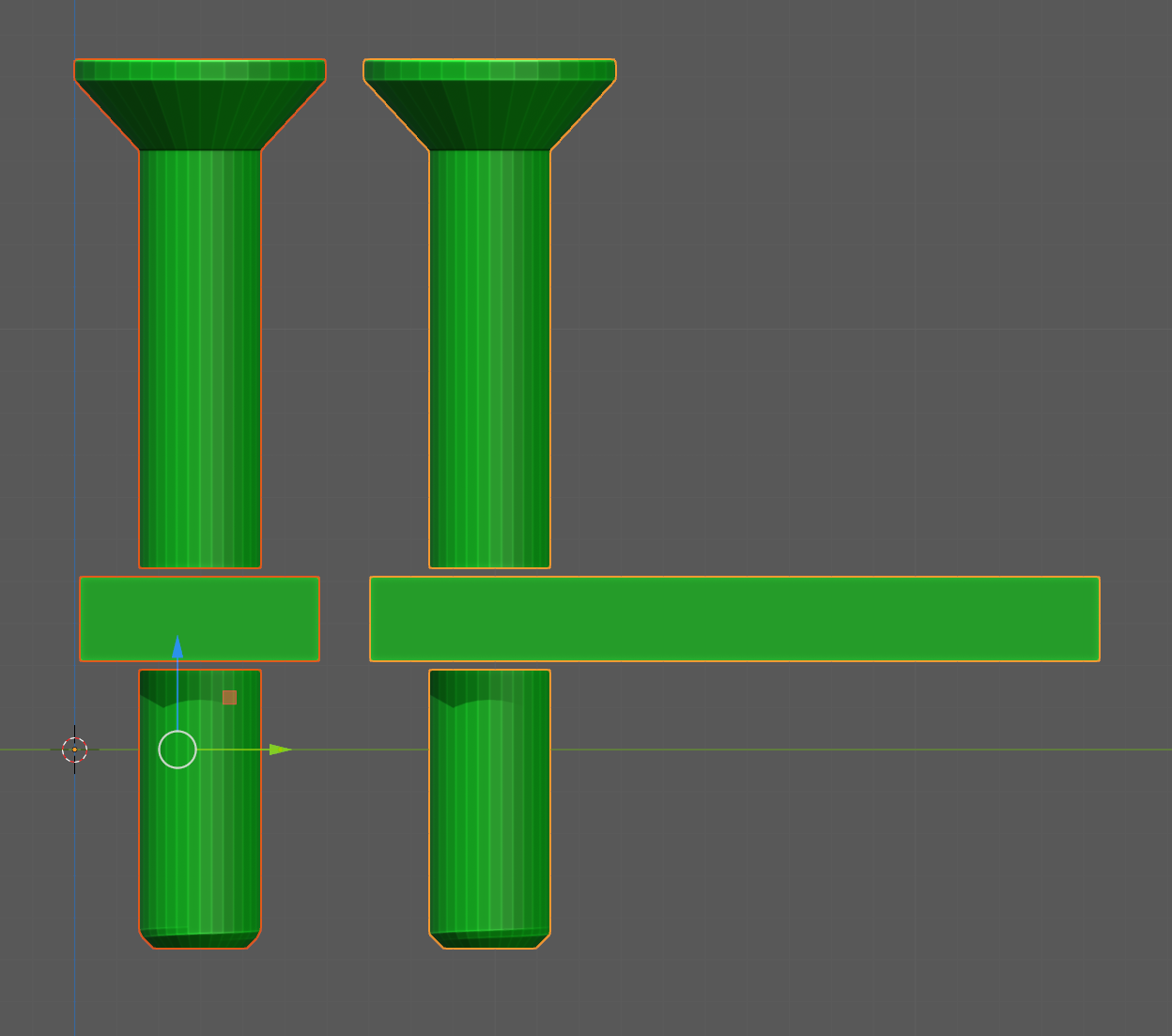
Here is a pic of the base model I use as a negative to cut out the holes for a M3 screw with square nut (Boolean subtraction). Side view in X and Y. I can stretch the pocket to meet the outside of the thing I am cutting into as well as adjust the length of the screw sections to get the pocket where ever I need it to be and for the screw to reach. In practice I has premade ones for the common screw lengths I use as well as variants for both countersunk (pictured) as well as cap head hex screws etc.
I know this is a good while after you posted that original reply and gave me a different explanation in another reply, when I asked if you could reword it. I've made my own cutouts for this now, even with some variations on them. (Like some with the added layer between the tube for the screw and the bolt square and some without it, for use in different printing orientations.) I just wanted to let you know that I tested with and without that gap/extra layer in different orientations. It's like you said - if the screw is vertical, they' make a big difference. Just wanted to add a "Thank you," because this was a major help on this issue.