How exactly to increase tension on X and Y Belts?
I am getting shifting that indicates that the Y belt is loose. The X axis appears okay.
I did a check of the tension.
Y is 298.
X is 294.
Both are too loose. I bought my MkIII pre assembled. Have looked carefully in the manual. It does not indicate exactly where I should look to use a wrench to tighten up the belts. My belts should be 240, =/- 40 according to Page 71 in my manual.
Please show me a video or photos and written instructions on how to tighten both belts?
Thank you so much !
Peter
Re: How exactly to increase tension on X and Y Belts?
I've found the 240 +/-40 values to be nearly unobtainable with my present belt adjustments maxed. And I've got my belts fairly tight, enough so I can feel the axis get harder to pull end-to-end (chassis flex). Also, I've adjusted belt tension from slack to tight and see only 10 points of change (you must run self test to see any change). My sense is these are unreliable indicators.
To adjust tension, check your manual. The X-Axis motor can pivot, and has a set screw for adjustment (loosen three mount screws first). The Y-Axis pulley is adjustable with two screws (it's designed to wobble a bit, and not be snug against the chassis). Adjustment range is about 2mm. If these adjustments aren't enough, belts need to be shortened by moving one end a full tooth.
Re: How exactly to increase tension on X and Y Belts?
I did some reading on Gates GT2 Belts... found a couple equations for setting tension to their specs based on deflection
Gates specs about 2 pounds of force for the deflection test. There is some confusion on my part with what they define as Span Length and Pitch Length. Most reading suggests it is the length of the belt between end points; some reading suggests it's the single free span being measured. When a pulley is involved, I can't help but think the full belt is involved, not just 1/2 of it. YMMV.
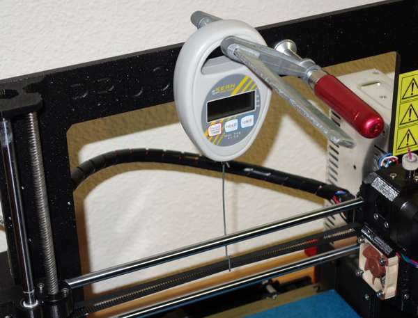
On my X-Axis belt, the free length is about 28 inches. At 2 lbs force, the belt should deflect 1/64" for every inch of length. Thus 28/64ths, or 7/16th. I probably erred on the tight side ... but in that range now. Prior adjustment had 1/8" deflection with an ounce. I used a trigger pull gauge to measure as accurately as I could. A fishing scale would work, too.
1/64 * 28 = 28/64 with 32 oz
I've adjusted the belts accordingly... and they seem pretty tight. Not quite a guitar string twang, but getting there. The printer seems to operate just fine - no noticeable hiccups so far. And it is a lot quieter.
I found it hard to find reliable Gates 2GT belt tension data... If anyone else knows where to find actual design specs for it, please post up.
More info at:
http://dpk3n3gg92jwt.cloudfront.net/gates.pt/pdf/drivedesign_powergrip.pdf
Re: How exactly to increase tension on X and Y Belts?
1/64 * 28 = 28/64 with 32 oz
This seems quite tight.
The correct belt tension depends on the application which, in our case, is a "registration drive", I guess. For a "registration drive", this document ( http://www.sdp-si.com/PDFS/Technical-Section-Timing.pdf ) recommends a "starting value" of 1.5 ...2 times the Tst value found in table 10. For a 2mm x 6mm GT3 belt (which I assume to be similar enough, in this respect, to a GT2 belt), table 10 lists a value of 3 lbs. So the lowest "starting value", which I deem quite high already, would be 1.5·3lbs= 4.5 lbs. The according deflection force for 1/64" deflection per inch of free span length can be calculated with formula 10-4. 't' is the span length, so the distance (one-way) between the two pulleys (motor - idler), and 'L' is basically the total belt length (or pitch line length). We only need the ratio, which is approximately t/L=1/2 in our case. 'Y' can be retrieved from table 9, so Y=2.05 (lbs, I guess). Note that table 9 also specifies a minimum Tst of 2 lbs, which I interpret as to be the absolute minimum, no matter what application. So for the necessary deflection force we finally get F = (Tst+t/L·Y)/16 = (4.5lbs+1/2*2lbs)/16 = 5.5lbs/16 = 0.34 lbs (0.19 lbs for Tst=2lbs. For my X belt I need about 0.24 lbs for pulling the lower span up by 6mm (~380mm/64), but the scale I used might not really be up for such low forces. I prefer anyway to go by the pluck frequency, which is way easier to measure and more precise (see also https://shop.prusa3d.com/forum/others-archive--f66/use-free-span-frequency-hz-to-check-and-set-belt-t-t12576-s10.html#p73398 ).
Re: How exactly to increase tension on X and Y Belts?
Here's the equations behind my numbers ... Note the second set of factors suggest a "typical" tension on a 1/4" belt of 45-65 pounds. That's a linear pull on the belt, not the deflection force. This linear tension is what the "frequency of resonance" will provide - all things being equal).
When installing the X-Axis motor, I had to firmly pull on it to set the belt -- no where near 50 pounds, but I was in the 5 to 10 pound range.

We are solving for Df with a Tst (static tension) of that 80 lb New Belt, 60 lb old belt, or 45-65 nominal tension,
-- I'll use 50 as my design goal
Tst = design static tension (50)
t = span length (15" approx)
L = belt pitch length (30" approx)
Y = Constant from Table 9 (dependent of belt design and materials) Gates 6mm GT3 is 2.0, Gates 1/4" industrial belt is 3.05.
Df = (Tst+(y/L)*2)/16
Df = ( 50 + (15/30) * 2) / 16 == ( 50 + 0.5 * 2 ) / 16 == (50 + 1 ) /16 == 51 / 16 == 3.38
At 3.4 lbs Df and 15" span, 15/64"deflection yields a 50 lb belt tension. The force vs tension relation ship is linear, so 1.7 lbs Df to get a 15/64" deflection yields 25 lbs tension, etc.
And remember: Belt minimum spec is 2 lbs static tension... 80 lbs is a recommended New Belt tension. On the other hand, one NEMA 17 motor I was able to find has a rated radial load of only 28 N -- about 6.6 lbf. A careful balance is probably in order.
To keep at 5 lbs tension: a Df of .34 lbs at 15/64 inch is required. Or 6 ounces at 1/8th inch.
Re: How exactly to increase tension on X and Y Belts?
Note the second set of factors suggest a "typical" tension on a 1/4" belt of 45-65 pounds. That's a linear pull on the belt, not the deflection force. This linear tension is what the "frequency of resonance" will provide - all things being equal).
Where did you get these numbers from? I am not sure about the absolute maximum, but the "Allowable Working Tension" for a GT2 2x6mm belt is 25lbf per inch belt width, i.e. about 25/4 = 6.25 lbf (table 3 in http://www.sdp-si.com/PDFS/Technical-Section-Timing.pdf ).
When installing the X-Axis motor, I had to firmly pull on it to set the belt -- no where near 50 pounds, but I was in the 5 to 10 pound range.
So the according belt tension would be half of that, i.e. 2.5 to 5 lbf (because if you pull at the motor, you are putting tension on two belt spans).
And remember: Belt minimum spec is 2 lbs static tension... 80 lbs is a recommended New Belt tension. On the other hand, one NEMA 17 motor I was able to find has a rated radial load of only 28 N -- about 6.6 lbf.
Yep. One could think that it is even worse, because there are two belt spans pulling at the motor axis, which would suggest 14N max belt tension. On the other hand, the 28N is specified for 20mm away from the motor's face plate, whereas the pulley is mounted closer than that (about 10mm). Assuming that the front bearing in the motor, probably located right behind the face plate, is the limiting factor, the motor should be good for a belt tension of maybe 25N.
Be it as it may. In my experience, these belts do not hold up to much more than 3lbs belt tension on the long run anyway, but I don't have hard data on that.
Re: How exactly to increase tension on X and Y Belts?
I think I finally found actual Gates GT2 belt working tension specs ... 111N or 25lbf per inch of width. Thus 6 lbf for a 6mm, more or less. Breaking strength is around 125 lbf for a 6mm belt.
Re: How exactly to increase tension on X and Y Belts?
I got with my friend who assembled and owns the MKIII. He showed me how to tighten the tension on X andY belts. We did so. We took both belts in 1 tooth, and then used the proper screws to set tension by feel.
The printer does NOT show any different numbers when I scroll to the menu that displays the X and Y belt numbers.
Yes, I turned off the printer. Transported it home. Did a full XYZ Axis calibration.
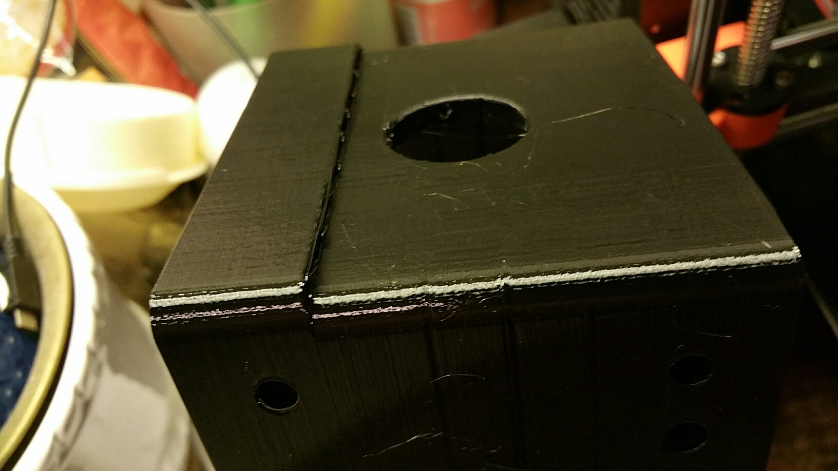
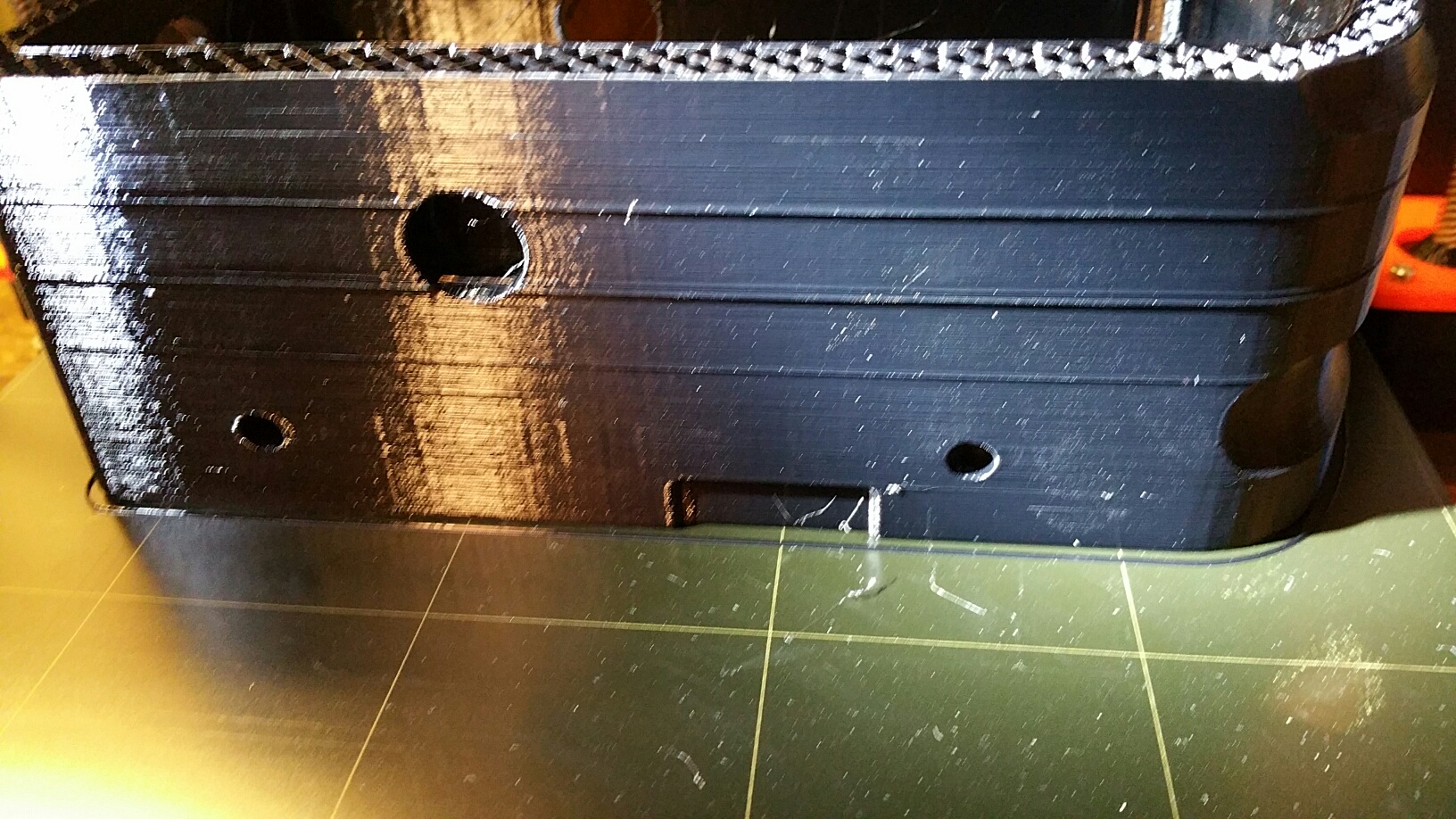
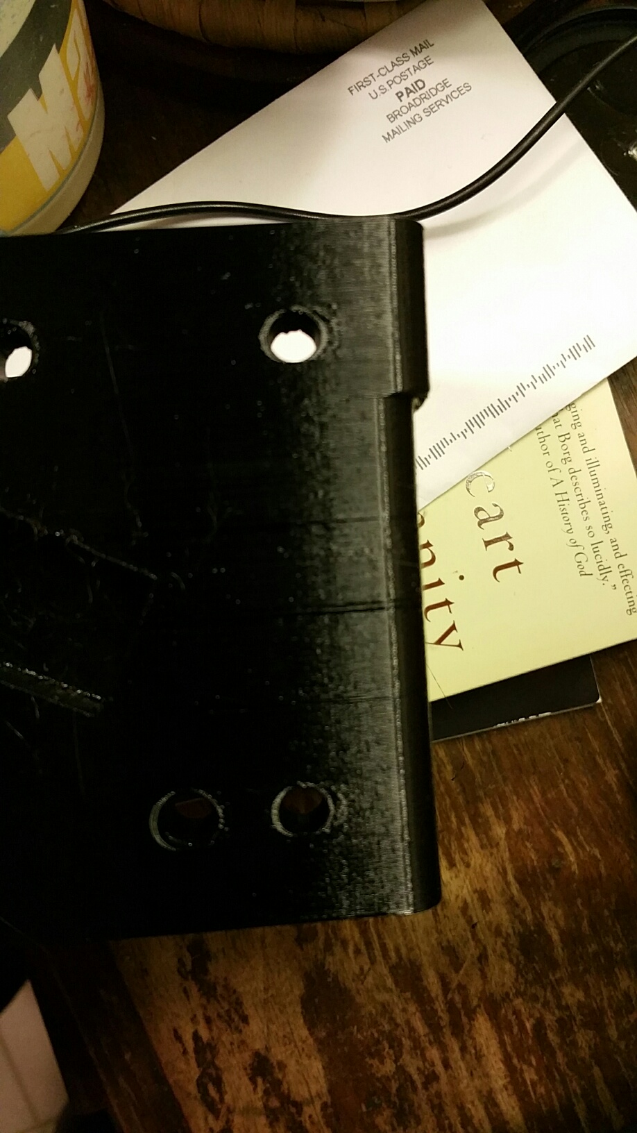
Now, instead of just the thin layer asymmetry, I have what the photos show. Thin layers- and suddenly a huge shift in the side to side axis ( the Y axis, yes? )
If the display does not show me the proper tension numbers, how am I supposed to fine-tune to try to eliminate the problems?? Not by feel and squeeze alone, surely??
Re: How exactly to increase tension on X and Y Belts?
The printer does NOT show any different numbers when I scroll to the menu that displays the X and Y belt numbers.
You run a self-test to update the tension numbers, according to the manual.
The only way to know what the tension is, is to measure it. "By Feel" doesn't work well. The support values are estimates, and can be tricked by many factors like bearing wear, maladjusted frame, etc. My numbers went from 277 to 285 - yet I went from an ounce of deflection pressure to 2 pounds of deflection pressure: yes, exactly opposite what the manual says should happen. Why? I also replaced the 2000 hour stock bearings with good bearings.
Re: How exactly to increase tension on X and Y Belts?
There was a note in the user maintenance instructions that says when plucked the belts should give a "Low Tone" i used a tuner app and my my voice to tune them to low A that is 220 Cycles per sec or Hertz... this number has no relation to the test numbers and my printer gives me 278 and 282 for X and Y on that test... but I still get random layer shifts every 5 or 6 prints that go over 4 hours almost always in the Y direction and of 3 to 5mm the rare x shifts are of 0.5 to 0.7 mm
Re: How exactly to increase tension on X and Y Belts?
There may be some merit to using a sound analyzer app. Lower frequency response would indicate a looser belt and higher frequencies would indicate tighter belt. There are several apps on google play that would serve this purpose.
All we would need is the frequency of a known good belt tension, then we could simply adjust to a frequency goal. Its not as dead-nuts accurate as a weight/force meter, but it would get us very close a given tension; this would be a great alternative.
Perhaps Prusa support or a prusa master jedi would perform the frequency check and post? I'm going to give this a go and will post my results either here or in a new thread. One should ENSURE their extruder is as far right as possible for measuring x axis, and bed is as far forward as possible when measuring the y axis.
cheers,
Chris
Re: How exactly to increase tension on X and Y Belts?
i used a tuner app on my iphone to give my voice a note.as I am a singer. The manual says some wher to shoot for a low tone so I selected A2 at 220 cycles per sec. (hertz in modern parlance) that got my belts to 268 for X and 272 for Y (i don't have perfect pitch) in the belt check on the printer tests note that those numbers do not translate to exact tension results other than a lower number is a tighter belt (and of course a higher number is a looser belt.
Re: How exactly to increase tension on X and Y Belts?
Sounds like a good target, Randolph. My hope would be to reduce ringing artifacts.
I'm a bit frustrated like the OP. What is a "low tone?" What is "some force". Such arbitrary terms in the manual. Sure guessing will work, but I think we'd all like to know something specific for optimal results. For someone who's into music, 40hz is a very low tone. 220hz is close to the midrange frequencies, but might sound low to some people. Ah well. Like I posted. I will do some testing. I suspect there is a point of diminishing return.
cheers,
Chris
Re: How exactly to increase tension on X and Y Belts?
I have the same frustration with instructions that are dumbed down for folks who have their mechanical aptitude tested putting together an IKEA side table, but I understand the necessity in a consumer kit product... in the 1960s Heath kit established the gold standard in complex kit instructions. and I can see Prusa striving in that direction but I wish they could also include more of an engineers set of instructions...
When I was assembling my kit I had to go to Machineries Handbook to get the proper torque setting for a SS M3 socket head cap screw into an Aluminum extrusion or a SS nut...
i settled on 10 inch pounds on my calibrated gunsmiths tool but others have pointed out that the torque wrenches that most hobbyists will have access to will seldom go that low and if they do they are notoriously inaccurate at these low values for small fasteners.
While the maker movement has helped bring back a lot of skills that I learned as small child in the 50s taking apart and then putting back things like cheap mechanical clocks and junk firearms and of course toys. back then most things were built to be repairable and by the 1970s more and more consumer products were marked "No User Serviceable Parts" and as a result... We have a generations of folks that have not developed these basic skills of how tight is tight enough and what is too tight where they are compromising the strength of the fastening .
Prusa is doing a great job with these instructions but lets look at any instruction that has more than a few comments in the online version of the manual if a step has more than a few comments that should be a flag that they should not just improve the manual ayt that point but that perhaps there should be some more than minor adjustments in that way it has been engineered. lets look at this step from this page https://manual.prusa3d.com/Guide/9.+Preflight+check/514#s8293
Release the screw holding the P.I.N.D.A. sensor and gently press it against the zip tie.
Move the extruder to the centre of the X-axis.
Take a zip tie from the package and place it under the P.I.N.D.A. sensor. Use the middle part of the zip tie, not the tip.
Release the screw holding the P.I.N.D.A. sensor and gently press it against the zip tie.
Tighten the screw on the P.I.N.D.A. holder again.
!!! DO NOT use glue to fix P.I.N.D.A. probe in the new type of holder with the M3 screw, you won't be able to release it again !!!
A correct height of the P.I.N.D.A. sensor compared to the nozzle should be similar to the last picture.
47 comments
There are no zip ties in the spare parts package. But there are plenty left in the zip tie bag, so i used one of them.
Michael Stegen - 12/05/2017
Hi Michael, step description updated 😉
Jakub Dolezal - 12/19/2017
I actually damaged my PEI surface on my mk2s build because of this recommendation to use a zip tie as a spacer/measuring tool. The same won't happen here since you do the initial calibration without the steel sheet installed (could be worse here if you did manage to crash the nozzle into the pcb though), but I would still suggest going by the 3rd image showing a front perspective of the relative gaps and just setting the position visually.
Steven Underwood - 12/14/2017
Always err on the side of caution. ITs better to have the pinda closer to the bed than higher. Too high, it will crash into the bed and ruin your day. You can always easy up on it later if you have to use a lot of negative Live Z adjustment to get your filament to stick.
Joe Bruno - 12/17/2017
On my Mk2, I measured the Zip tie and came up with 0.975mm when the recommended height was 1.2mm. Because of a slight bed warping, that caused my first print calibration to continually fail, I backed off the height over that point (right rear) to 1.0 mm and I was able to calibrate and print.
James Slater - 12/17/2017
How hard I need to turn the points screw? I did not tighten it to hard but the plastic holder banded and I’m afraid it will break in future.
יוסי שלי - 12/21/2017
Hi, the screw should be tightened so the probe doesn’t move. No need to overtighten the screw as you might break the printed part.
Jakub Dolezal - January 2
So, now that the P.I.N.D.A. is set to the correct hight, what is next exactly? Should the Z-axis be moved up again or can the selftest be started with the Z-axis in the lowest position? Perhaps it should actually be in this position for the selftest to work? Missing a bit of detail here I’m afraid.
Jeroen - 12/21/2017
Hi Jeroen, regarding the next step, see the video (Step 4) and follow the 3D Handbook. As for now there is no need to adjust the Z-axis manually 😉
Jakub Dolezal - January 2
I used one of the pieces of excess length trimmed from a zip tie.
Bruce Moore - 12/29/2017
Are we to assume that the nozzle is touching the pcb during this step or is it just slightly above? Could we do the step of pinda probe height with a piece of paper underneath to protect the nozzle/pcb from getting damaged?
Since the paper would go under both the pinda and the nozzle it wouldn’t affect the adjustment.
Matty vee - January 22
Exactly, there is no mention of nozzle touching bed, whilst actually adjusting probe. Also as I said before, sheet of printer paper is an excellent idea!
Gary Walker - August 3
Hmmm… I have the spring steel sheet that magnetically attaches to the heated bed. Don’t you need to add that before doing the calibration adjustments??
Mr Cookie - January 29
Hi Mr Cookie, for now please do not use the spring steel sheet, follow the manual 😉
Jakub Dolezal - January 31
Had problems adjusting the P.IN.D.A. It was tight in its holder even with the screw released so I had to twist it so that the threads on its body would lower it. Fortunately I left enough lead free at the P.IN.D.A. end so it was able to coil up as the P.IN.D.A screwed down. If this is a common problem either a reworking on the P.IN.D.A mount’s tolerances or a simpler change the photo of the preliminary positioning of the P.IN.D.A. in section 5 the E-Axis should show the P.IN.D.A. in a lower nominal position.
Martin Wolfe - February 7
I had a simliar issue. the P.I.N.D.A. mount is tight enough that even without the screw I can’t push it down without turning the actual sensor to screw it further in.
Chris Schmitz - February 11
Same as above!
Gary Walker - August 3
Yes - the PINDA is very hard to move up/down at this stage.
Jascha Narveson - August 20
I’ll just add my voice to the choir of people complaining about how tight the PINDA is. It’s extremely frustrating.
Jascha Narveson - August 20
Ditto - very difficult to finely adjust the PINDA probe.
Liquidlogic - 5 days ago
I am amending my previous comment slightly as I had the extruder in the wrong position. However the P.IN.D.A mount / body interface needs to reworked. Perhaps a collet around the P.IN.D.A. so that it can slide up and down freely when the adjustment screw is loosened.
Martin Wolfe - February 7
Instead of this sentence which is vague as to what the last picture is: “A correct height of the P.I.N.D.A. sensor compared to the nozzle should be similar to the last picture. “ Label one of the pictures and call it out specifically” such as “A correct height of the P.I.N.D.A. sensor compared to the nozzle should be similar to the picture ‘Correct PINDA Height’ “
greg mesh - February 19
Hi Greg, “correct PINDA height” is not the same for all printers. This device has certain range of sensitivity and each unit is therefore slightly different. That is why you need to go through calibration process .
Jakub Dolezal - February 20
From my tests it is best to move the nozzle so it almost touches the bed (you can slide thin paper [thinner than normal office paper] under it with some but small resistance), then PINDA sensor should be 11 layers of standard office printer paper (A4 for Laser printers) above the bed. I think that is a bit more accurate than using zip tie method. 10 or 12 layers would also work too. I do not have calipers or dial indicator holder with me to determine the height exactly at the moment.
Witold Baryluk - April 5
The zip tie is about 1.2mm thick. For me to pass calibration (next step), I need to lower the PINDA probe to about 0.65mm (by using 9 sheets of paper) in order for it to properly calibrate .. without doing that the extrusion nozzle was hitting the bed, so you need to get the probe low.
Also at this point I was confused about the metal sheet … this is not used until after initial system checks (fans, hot-end, xyz axis, xyz calibration). It is put on right before the printing of first-layer calibration.
Gerry P - April 6
Same here, in the sense that with zip-tie height, the nozzle just crashes into the heatbed. I almost can’t believe I followed 9 sections of assembly instructions to the letter and to then just see the extruder going down endlessly. I now even dropped the PINDA probe to below the nozzle. Not a workable solution but I wanted to see if calibration in general would continue properly. Not sure what to do now. What is the minimal height above the nozzle the PINDA probe should be to not have it bump into the print?
Christophe Lermytte - June 8
I had to lower the pinda beyond zip tie thickness as well. Nozzle crashed into the bed during calibration.
Vince - April 28
PINDA isn’t moving the slightest bit with completely los screw and holder.. No idea how to proceed here. Also how am I going to place the steel sheet back in as the next step (calibration of Z axis) asks me to to, while the nozzle is still touching the heated bed?
Lennart - April 29
I put in a screw driver to force open the clamp then it went down. still problems getting to engage at 1.2mm so per text above placed it slightly lower.
vincent bartlett - May 12
Thank you Vincent, the screwdriver to open up the clamp just a tiny bit to let me move the sensor helped - mine wasn’t moving otherwise.
Gregory Thomson - June 10
I too had a Pinda sensor that was too tight. Fed up with the clearances in the plastic, I used a hobby knife to cut the two small bridges on the back of the Pinda holder, placed a small screwdriver into the slot of the holder, then pressed the screwdriver handle to one side (I didn’t twist it) until I could move the Pinda sensor. That worked fine for me.
Brad Needham - August 14
The pinda alignment crap has made the pre-flight stage !&&*. The pinder sensor has deep rings that grip the pinda mount hole tightly even without the damned screw! I don’t even need the screw because I can only move the sensor using the pliers. Absolute nightmare.
Raphael Baker - June 8
I have to say the PINDA on mine was very hard to move easily in the holder, more space is needed to make this part easier without stress on the extruded head while trying to make the PINDA move…
Martin Wright - June 11
Hi Martin, based on the feedback I already asked devs to update the parts and PIDNA holder is among them.
Jakub Dolezal - June 12
Wowww. This step really made me angry & frustrated. It would have been so much easier to do this when I initally put the PINDA in. The PINDA does not budge at all within its part very easily and takes more leverage than I can give it fully assembled without risking damage. I could have easily made this adjustment when I initially put the E-Axis together. Now I will have to take it apart just to align the PINDA. I feel you in that writing a build sheet is very tedious and all that, but this is a rookie mistake. Super frustrating considering I just finished the entire build.
Zaki Ullah - June 24
Moving the Pinda probe vertically was almost impossible : it is gripped statically by the holding plastic component, even with the screw loose. A flat bladed screw driver from above, into the slot at the end of the Pinda holding component, twisted slightly, allowed us to release it to easily be pushed down onto the zip tie.
Jonathan Histed - June 29
A panel nut (aka "jam nut") on the top and bottom of the PINDA mount would allow one to pull the PINDA sensor up or down as needed with much greater precision.
It appears the PINDA sensor has M8x1.00 threads. If so, examples would be: Grainger 38DG64 Zinc Plated "Thin Nut", or Fastenal MJ2590000ZP0000 "M8-1.0 DIN 439B Class 04 Zinc Finish Steel Jam Nut " or Fastenal MJ2590000PF0000 "M8-1.0 DIN 439B Class 04 Plain Finish Steel Jam Nut". Ideally, these would be installed between Steps 23 and 24 of section 5.
Mine is stuck, but I was blindly lucky and happen to have placed it very close to the specified position (actually, with slightly less gap than specified but this err’s on the side of safety). If it helps anyone, upon inspection, mine has a single layer“web” of plastic holding the gap in a fixed position (the “gap” is the opening that the clamping screw would pull closed to hold the PINDA in place). Cutting this web may make this much easier to adjust.
MattP - July 1
After turning on my printer for the first time the LCD switches between two screens saying “printer has not been calibrated yet. Please follow the manual, chapter” and the next screen says “First steps section, calibration flow”. Pressing the reset button only brings me back to this menu switching between the two screens. Turning the dial does nothing. I am stuck.
Robert Morgan - July 1
Hi Robert, please try upgrading the firmware: Upgrading the firmware v1.4 if it doesn't help, please contact our support at [email protected]
Jakub Dolezal - July 2
I have endlessly adjusted the PINDA and the calibration still fails. I am beyond frustrated. I have double checked all connections just to be sure something was not lose or in the way, hotend and sensor etc. Uggggggg.
Erik Kometti - July 26
I found an easy way to adjust the PINDA. Loosen the screw as described and with a very small (jewellers) flat screw driver, place it in one of the notches close under the plastic holder and gently lever against the plastic, this moves it with extreme precision.
Rod Lewin - July 27
1- To fix my calibration I had to redo (9. Preflight check): In the section(P.I.N.D.A. adjustment (part 2)) while moving the extruder from left to right, I added a white sheet under the nozzle. Im my case, I don’t wanted the nozzle no be able to move my flat white sheet (new paper). While moving the extruder to the right, if the sheet moved, I adjusted the height of the right rail.
2- Prusa tie rap height: 1.1mm.
3- When I put the tie under the PINDA, my tie rap had to be able to move with a really little pressure.
4- My bed had to be clean and heated at 60 degrees. (If I use windex with ammoniac, I have to put a really light level of glue provided by Prusa called Kores. (Sometime I have to Preheat the nozzle as 230 degrees with a bed of 85 degrees (PET), then I changed to PLA(215/60)) than way my bed will be optimal. For me, I never put the glue when the bed is not at 60 degrees, if not it failed or slide the first layer
5- Last step is to redo the first layer test until the height is good
Thanks. Steven.
Steven Alex - August 11
Whoa. This part is really important and repetitive. Pressing the zip tie flat, if the probe is one click higher than the zip tie, then the Z calibration during First Layer Calibration requires you to lower the head past -1mm to get a squished, but not see-through bead and if it’s one click below where the zip tie won’t fit underneath, then the nozzle snags the paper during calibration. I found myself having success in twisting the probe, since it has threads on the probe and the printed part, then holding the probe while I tightened it down. I hope I’m doing this right… this is my first time at this and I still can’t get the extruded filament to properly spread out and fill the gaps in-between the rows of filament.
Zerg620 - August 29
Why I usually live by the “a thumb’s width, give or take a whisker” approach myself - as this will be the first time I’ll be doing this, I’d appreciate some numbers for the recommended distances for both the nozzle and the probe at this step. Feeler gauges are cheap.
I’ve seen the information somewhere on the forum (IIRC, the probe should be 0.5 mm higher than the nozzle, which is somewhat compatible to the numbers in the other comments), but putting these numbers, even just as a side remark, in the instructions, would be helpful.
Markus Imhof - October 10
Hello Markus, measuring this distance properly and accurately can be tricky, that is why we recommend using the zip tie as a reference - it is in the package and has just the right size.
Martin L. - Customer Support - October 11
I had no gummy bears left! 🙁 For all of the hardwork, we need more than one pack. Please take note. 😀
Ademola - November 5
Unlike others my PINDA probe is moveable HOWEVER the way it’s designed makes it almost impossible to adjust linearly in small amounts. The PINDA probe has large threads that either leave a thread imprint in the holder after its tightened or catches on the printed layers or both, but the result is it moves in increments of steps instead of linearly. If the probe had no threads it would be far easier to adjust.
Ybl84f1 - November 29
Re: How exactly to increase tension on X and Y Belts?
I think I finally found actual Gates GT2 belt working tension specs ...
Re: How exactly to increase tension on X and Y Belts?
I think I finally found actual Gates GT2 belt working tension specs ...
Where and what did you find? And how to test tension according to Gates?
Re: How exactly to increase tension on X and Y Belts?
As an FYI - the tension model using two points, one is a motor the other is the load. Both are geared pulleys that lock the belt into two spans. In our printers, one of the ends is a free wheel, so the span is the 'free' length of the belt, not the distance between pulleys. Thus from motor gear around pulley back to extruder is the length for the stretch calculations. And if power is off, and the motor free to turn, then the entire belt becomes the span.
This probably doesn't affect the frequency test... but someone should ask an ME.
Re: How exactly to increase tension on X and Y Belts?
I had the same discussion since a few days in another thread:
I didn't have problems for the Y belt, as it's fairly easy to adjust. My concern was mostly X.
If you look at the thread, you can see the tension/frequency I determined on the X belt.